


automotive
#LED array
#visual alert
#brake light
#flasher
#vehicle safety
#oscillator
#IC
#automotive lighting
#visibility
#conspicuity

Description: Circuits of this type are designed to drive LED arrays to enhance visibility and conspicuity when a vehicle is stopped or slowing down. This specific circuit emits a visual alerting signal consisting of four short flashes followed by a steady light that remains illuminated as long as the brakes are applied. The internal oscillator of IC1 generates a square wave, which is divided 64 times by the flip-flops within the chip to achieve a frequency of approximately 1 to 4 Hz at pin #4. This frequency corresponds to the LED array's flashing rate and can be adjusted to the desired value using resistor R3. A positive signal at the cathode of diode D1 halts the oscillator after five pulses have been counted. Capacitor C2 and resistor R1 automatically reset the IC whenever the brakes are engaged. Transistor Q1 serves as the driver for the LED array, causing the LEDs to illuminate when pin #4 of IC1 goes low.
The described circuit employs a combination of digital and analog components to manage the operation of an LED array effectively. The use of an integrated circuit (IC) as the core of the design allows for precise control over the flashing and steady illumination of the LEDs, which is crucial for alerting other drivers. The internal oscillator's square wave output is a key feature, as it provides the timing necessary for the visual alerts. The frequency division by the flip-flops ensures that the output signal remains in an optimal range for visibility without causing distraction.
The adjustment of the flashing frequency through resistor R3 enables customization based on specific application requirements or regulatory standards. This flexibility is important for different vehicle types or environments. The inclusion of diode D1 serves a critical role in controlling the duration of the flashing sequence; once five pulses are counted, the circuit transitions to the steady-on mode. This transition is vital for ensuring that the vehicle remains visible during the braking process.
The automatic reset functionality provided by capacitor C2 and resistor R1 ensures that the circuit is responsive to brake engagement. This feature enhances safety by making certain that the LED array is activated promptly whenever the brakes are applied. The use of transistor Q1 as the driver for the LED array allows for efficient control of the high current needed to illuminate multiple LEDs, ensuring that they operate within their specified parameters without risk of damage.
Overall, this circuit design effectively combines various electronic components to create a reliable and visually effective alert system for vehicles, enhancing safety and visibility in critical situations.Circuits of this kind are intended to drive LED Arrays in order to create more visibility and conspicuity when a vehicle is stopped or stopping. This circuit, in particular, will emit a visual alerting signal of 4 short flashes, followed by a steady on light that remains steady on as long as the brakes are applied.
IC1 internal oscillator generate s a square wave whose frequency is divided 64 times by the flip-flops contained in the chip in order to obtain about 1 to 4Hz at pin #4: this is the LED Array flashing frequency and can be set to the desired value by means of R3. A positive signal at D1 Cathode stops the oscillator after 5 pulses are counted. C2 and R1 automatically reset the IC whenever the brakes are applied. Q1 is the LED Array driver: LEDs will be on when pin #4 of IC1 goes low.
The described circuit employs a combination of digital and analog components to manage the operation of an LED array effectively. The use of an integrated circuit (IC) as the core of the design allows for precise control over the flashing and steady illumination of the LEDs, which is crucial for alerting other drivers. The internal oscillator's square wave output is a key feature, as it provides the timing necessary for the visual alerts. The frequency division by the flip-flops ensures that the output signal remains in an optimal range for visibility without causing distraction.
The adjustment of the flashing frequency through resistor R3 enables customization based on specific application requirements or regulatory standards. This flexibility is important for different vehicle types or environments. The inclusion of diode D1 serves a critical role in controlling the duration of the flashing sequence; once five pulses are counted, the circuit transitions to the steady-on mode. This transition is vital for ensuring that the vehicle remains visible during the braking process.
The automatic reset functionality provided by capacitor C2 and resistor R1 ensures that the circuit is responsive to brake engagement. This feature enhances safety by making certain that the LED array is activated promptly whenever the brakes are applied. The use of transistor Q1 as the driver for the LED array allows for efficient control of the high current needed to illuminate multiple LEDs, ensuring that they operate within their specified parameters without risk of damage.
Overall, this circuit design effectively combines various electronic components to create a reliable and visually effective alert system for vehicles, enhancing safety and visibility in critical situations.Circuits of this kind are intended to drive LED Arrays in order to create more visibility and conspicuity when a vehicle is stopped or stopping. This circuit, in particular, will emit a visual alerting signal of 4 short flashes, followed by a steady on light that remains steady on as long as the brakes are applied.
IC1 internal oscillator generate s a square wave whose frequency is divided 64 times by the flip-flops contained in the chip in order to obtain about 1 to 4Hz at pin #4: this is the LED Array flashing frequency and can be set to the desired value by means of R3. A positive signal at D1 Cathode stops the oscillator after 5 pulses are counted. C2 and R1 automatically reset the IC whenever the brakes are applied. Q1 is the LED Array driver: LEDs will be on when pin #4 of IC1 goes low.
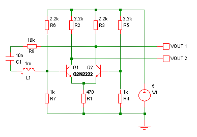
why doesnt this circuit oscillate
The buba oscillator initially failed to oscillate. The first step is to check the fundamental components, as minor errors in the values of capacitors, resistors, and inductors can significantly impact performance. It is advisable to measure component values with a...
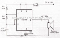
ring bell electronic circuit
This circuit generates an oscillating frequency of approximately 1 kHz, which can be adjusted by changing the value of resistor R1. The speaker will emit a continuous beep sound at this frequency.
The circuit utilizes a basic oscillator configuration, likely...
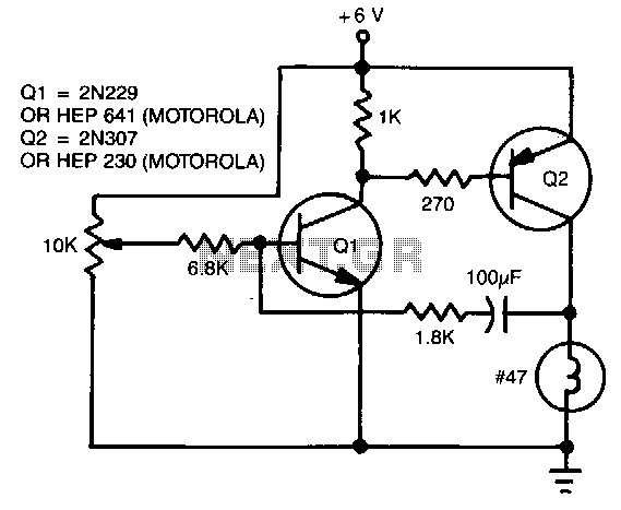
Single-lamp-flasher
The flash rate is controlled by a complementary multivibrator consisting of an NPN and a PNP transistor.
The complementary multivibrator circuit is a fundamental electronic configuration used to generate square wave signals, which can be employed for various applications including flashing...
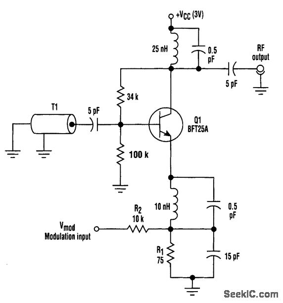
FM HF OSCILLATOR WITH NO VARACTOR
This circuit utilizes base-charging capacitance modulation instead of a varactor to frequency-modulate a high-frequency oscillator. This approach eliminates the significant voltage change required by a varactor, which can pose challenges in battery-powered systems with limited supply voltages. T1 serves as...
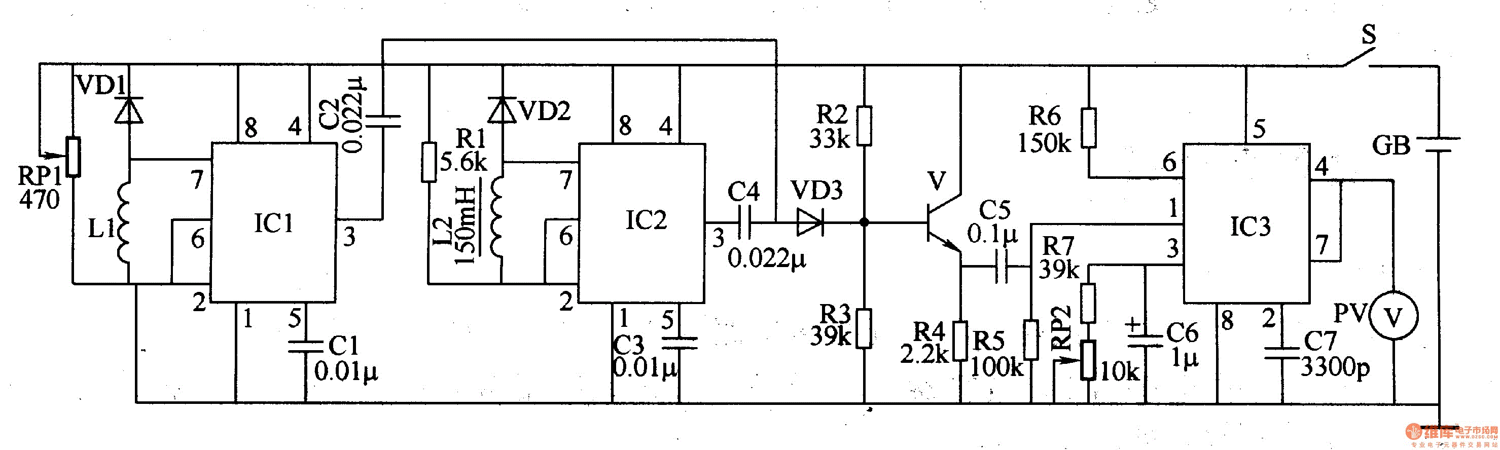
Metal detector 4
The metal detector circuit comprises a detection oscillator, a reference oscillator, a mixer, and a signal display, as illustrated in Figure 8-70. The detection oscillator circuit is made up of the time base oscillator IC1, inductor L1, potentiometer RP1, diode...

oscillator
An oscillator is an electronic circuit that converts energy from a direct-current source into a periodically varying electric output.
An oscillator is a fundamental component in various electronic systems, serving the purpose of generating oscillating signals, typically in the form of...
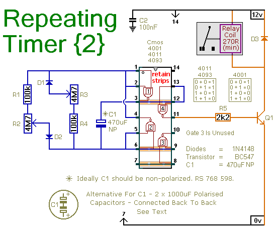
A Repeating Timer Circuit
This circuit is based on a simple asymmetric oscillator. The duration for which the relay remains energized and the duration for which it remains de-energized are independently set. With the component values indicated in the diagram, both durations are adjustable...
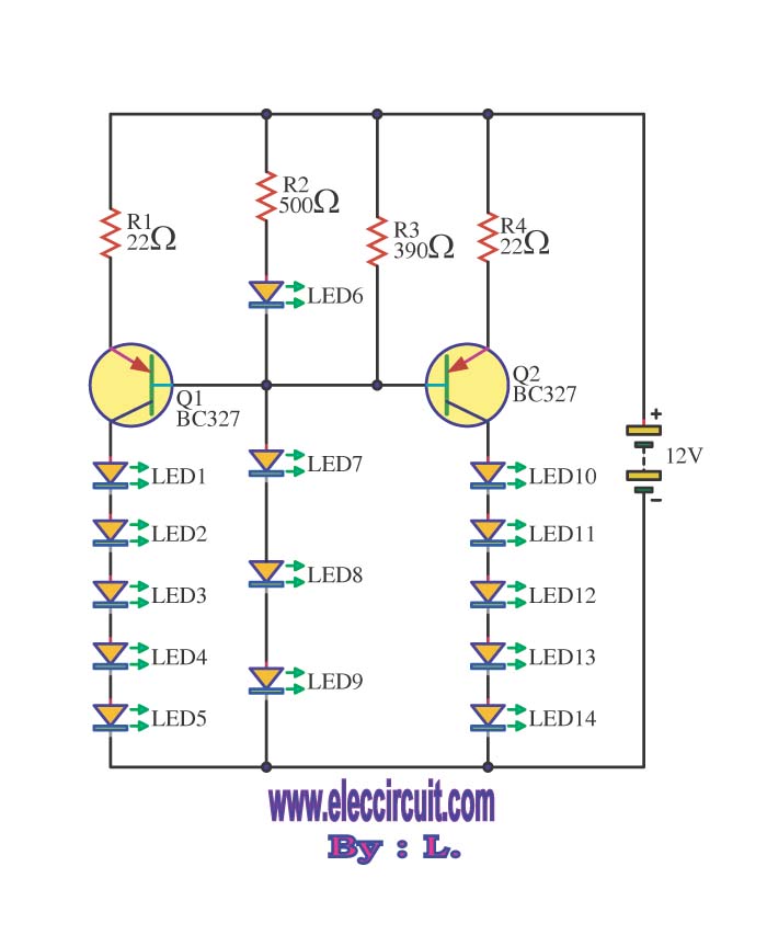
Brake lights flasher circuits
This circuit enables the brake light to flash. The default behavior occurs when power is supplied to the circuit or when the brake is engaged. The timer IC (IC2) drives current to the transistor (Q2), producing an oscillating output pulse...
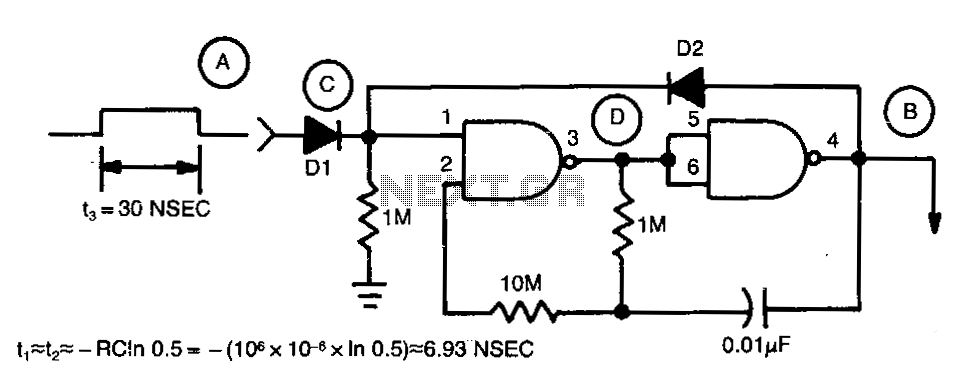
Last-cycle-completing-gated-oscillator
Regenerative feedback at capacitor C allows the oscillator to complete its timing cycle instead of shutting off immediately. The integrated circuit (IC) used was a CD4011AE, although an equivalent IC will also function.
The described circuit utilizes regenerative feedback to enhance...