


Back-up-beeper
#back-up beeper
#556 timer
#oscillator
#audible alert
#automotive safety
#pulse generator
#timer circuit
#reverse signal
#1Hz frequency
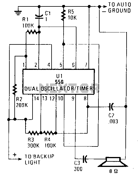
Description: When the vehicle is placed in reverse, the circuit emits a loud beep at a frequency of approximately one beep per second (1Hz). Half of the U1 component, a 556 dual oscillator/timer, functions as a slow-pulse oscillator with a frequency of about 1Hz. The resistors R2 and R1, along with capacitor C1, create a long time constant. The on time can be calculated using the formula t ≈ 0.7 (R1 + R2) C1, resulting in approximately 1.15 seconds. The off time is shorter, approximately 0.77 seconds. The enabling pin 4 (reset) is held high to maintain the oscillator in a free-running state when voltage is applied to pin 14. Additionally, the output at pin 5 is connected to pin 10 of U1, activating the second oscillator. The second oscillator generates an audio output of about 1 kHz, determined by components C2, R3, and R4. Pin 10 (reset) of the second oscillator is linked to the output at pin 5 of the first oscillator. When pin 5 goes high, the second oscillator produces a short pulsed tone at 1 kHz.
The described circuit utilizes a 556 dual timer IC, which contains two independent oscillators. The first oscillator operates at a low frequency of approximately 1Hz, generating a long-duration pulse that serves to alert the driver when the vehicle is in reverse. The timing components, R1, R2, and C1, are chosen to establish the desired time constant, allowing for a clear distinction between the on and off states of the output signal. The calculated on time of approximately 1.15 seconds ensures that the beep is sufficiently long to be noticeable, while the off time of 0.77 seconds helps to create a rhythmic beeping sound.
The second oscillator, activated through pin 5 of the first oscillator, is configured to produce a higher frequency output of about 1 kHz. This frequency is suitable for generating an audible alert that is easily recognizable. The timing components for this oscillator, C2, R3, and R4, are selected to achieve the desired frequency. The connection between pin 5 of the first oscillator and pin 10 of the second oscillator allows for the first oscillator's output to trigger the second oscillator, leading to a short pulsed tone whenever the first oscillator output transitions high. This design ensures that the alert sound is both effective and distinct, providing a clear warning to the driver when the vehicle is in reverse.
Overall, this circuit design effectively combines both low and high-frequency oscillators to create a practical auditory alert system for vehicles, enhancing safety by ensuring that the driver is alerted when the vehicle is in reverse gear. The careful selection of timing components and the configuration of the oscillators are crucial to achieving the desired performance of the circuit.Put the car in reverse and the circuit provides a loud, audible beep at the rate of about one per second (1Hz). Half of U1, a 556 dual oscillator/timer, is used as a slow-pulse oscillator with a rate of about 1Hz.
Components R2, R1, and C1 form the long time constant. You can calculate on time by t~.7 (R1 + R2) C1 or 1.15 seconds. The off time is shorter than the on time, at . 77 second. Enabling pin 4 (reset) is held high to keep the oscillator freerunning when voltage is applied to pin 14. The output at pin 5 is coupled to pin 10 of U1 enabling oscillator 2. Oscillator 2 of U1 produces an audio output of about 1 kHz, as determined by C2, R3, and R4. Pin 10 (reset) of oscillator 2 is connected to the pin 5 output of oscillator 1. Sn when pin 5 becomes positive, the oscillator beeps a short pulsed tone of 1 kHz.
The described circuit utilizes a 556 dual timer IC, which contains two independent oscillators. The first oscillator operates at a low frequency of approximately 1Hz, generating a long-duration pulse that serves to alert the driver when the vehicle is in reverse. The timing components, R1, R2, and C1, are chosen to establish the desired time constant, allowing for a clear distinction between the on and off states of the output signal. The calculated on time of approximately 1.15 seconds ensures that the beep is sufficiently long to be noticeable, while the off time of 0.77 seconds helps to create a rhythmic beeping sound.
The second oscillator, activated through pin 5 of the first oscillator, is configured to produce a higher frequency output of about 1 kHz. This frequency is suitable for generating an audible alert that is easily recognizable. The timing components for this oscillator, C2, R3, and R4, are selected to achieve the desired frequency. The connection between pin 5 of the first oscillator and pin 10 of the second oscillator allows for the first oscillator's output to trigger the second oscillator, leading to a short pulsed tone whenever the first oscillator output transitions high. This design ensures that the alert sound is both effective and distinct, providing a clear warning to the driver when the vehicle is in reverse.
Overall, this circuit design effectively combines both low and high-frequency oscillators to create a practical auditory alert system for vehicles, enhancing safety by ensuring that the driver is alerted when the vehicle is in reverse gear. The careful selection of timing components and the configuration of the oscillators are crucial to achieving the desired performance of the circuit.Put the car in reverse and the circuit provides a loud, audible beep at the rate of about one per second (1Hz). Half of U1, a 556 dual oscillator/timer, is used as a slow-pulse oscillator with a rate of about 1Hz.
Components R2, R1, and C1 form the long time constant. You can calculate on time by t~.7 (R1 + R2) C1 or 1.15 seconds. The off time is shorter than the on time, at . 77 second. Enabling pin 4 (reset) is held high to keep the oscillator freerunning when voltage is applied to pin 14. The output at pin 5 is coupled to pin 10 of U1 enabling oscillator 2. Oscillator 2 of U1 produces an audio output of about 1 kHz, as determined by C2, R3, and R4. Pin 10 (reset) of oscillator 2 is connected to the pin 5 output of oscillator 1. Sn when pin 5 becomes positive, the oscillator beeps a short pulsed tone of 1 kHz.
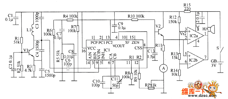
Metal detector circuit diagram 8
The metal detector circuit consists of a probe oscillator, a PLL (phase-locked loop) circuit, and an audio alarm circuit. The probe oscillator includes a detection coil (L), transistor (V1), and several resistors (R1 to R3) and capacitors (C1 to C5)....
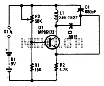
Minimal metal detector
This circuit is an oscillator with LI being a 4-inch diameter coil consisting of 35 turns of #26 magnet wire. Metal in proximity to LI will cause the oscillator to shift frequency. An AM transistor radio is used to detect...
automatic dual output display circuit diagram
This circuit lights up ten bulbs sequentially, first in one direction and then in the opposite direction, creating an appealing visual effect. In this circuit, gates N1 and N2 form an oscillator. The output of this oscillator serves as a...
Versatile two-phase pulse generator
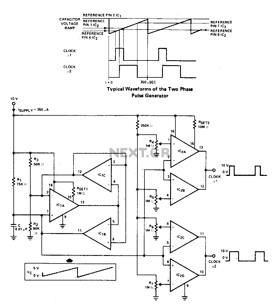
A two-phase clock generator utilizes two L161 integrated circuits to produce pulses with adjustable widths and phase relationships. Additionally, a ramp generator supplies input to two variable window comparators, which are configured using IC2A-IC2B and IC2C-IC2D, respectively.
The two-phase clock generator...
Simple Pulse Generator
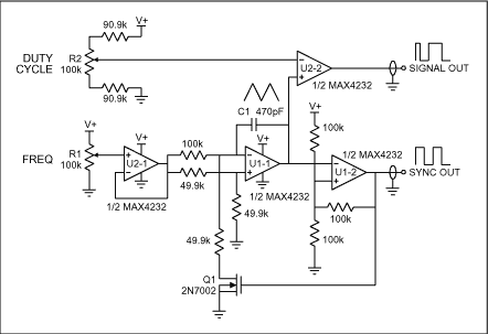
A pulse generator typically allows control over the pulse repetition rate, pulse width, pulse delay, and pulse amplitude. More advanced pulse generators may also enable adjustments to the rise time and fall time of the pulses. The delay of a...

Pulse Generator Circuit
By utilizing a 556 dual timer, with IC1A functioning as a waveshaper and IC1B as a pulse generator, a pulse width range of 10:1 can be achieved. This circuit can be triggered using a sine wave.
The circuit operates on the...
About Area 50
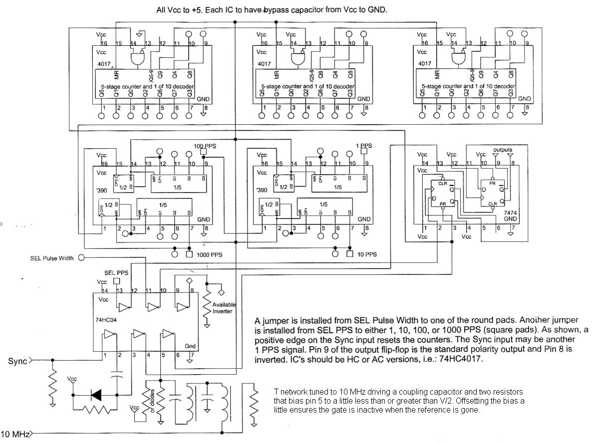
This circuit divides a 10 MHz reference signal to produce outputs of 1, 10, 100, or 1000 pulses per second. The pulse width can be selected using jumpers, offering multiple options. A synchronization input aligns the output pulses with an...
Double oscillator metal detector
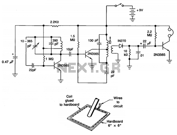
The circuit consists of two oscillators, both working at about 465 kHz. One uses an if transformer and the other uses an inductor (the search coil LI). The oscillators are coupled by a capacitor (10 pF). A beat note (produced...
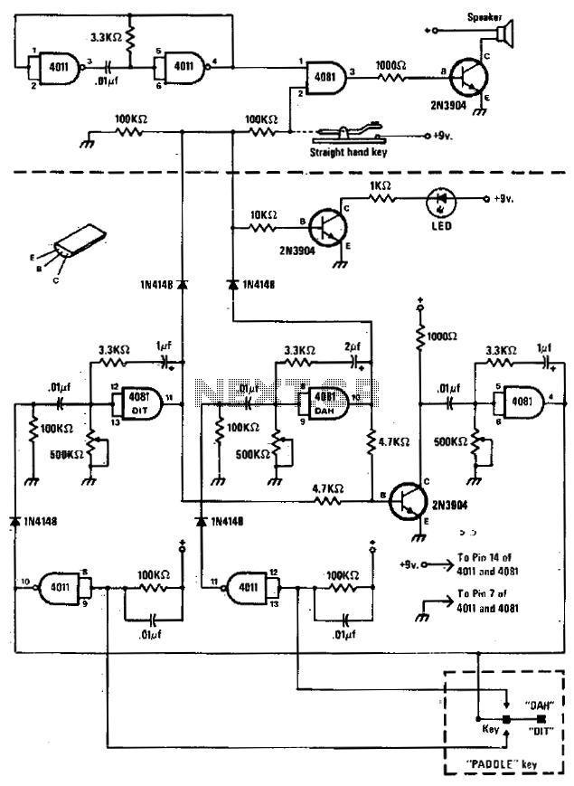
Code practice oscillator
The circuit comprises a basic oscillator (above the dashed line) and an automatic keyer (below the dashed line). The unit can be utilized with either a straight hand key or a paddle key for automatic operation.
The described circuit integrates two...