


Backup Beeper
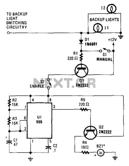
Description: When the vehicle's backup lights are activated, or when the manual switch (SI) is closed, a small current is supplied to the base of Q1. Transistor Q1 allows current to flow through it and, if the enable switch (S2) is closed, it sends 12 V to U1, a 555 timer. Timer U1 generates high pulses lasting 0.97713 seconds and low signals lasting 0.488565 seconds to the base of Q2. When U1 activates Q2, it sends 12 V to BZ1, a piezoelectric buzzer. For optimal performance, the buzzer should be installed under the vehicle in a location where it can be easily heard by individuals nearby.
The described circuit is designed to provide an audible warning when a vehicle is in reverse. The operation begins with the activation of the vehicle’s backup lights or the manual switch (SI). This action allows a small current to flow into the base of transistor Q1, which acts as a switch that controls the larger current flowing through the circuit.
When Q1 is activated, it allows current to pass through to the enable switch (S2). If switch S2 is closed, it energizes the 555 timer (U1) with a supply voltage of 12 V. The 555 timer is configured in astable mode, producing a continuous square wave output. The timer generates high pulses of approximately 0.97713 seconds and low signals of about 0.488565 seconds. These pulses are directed to the base of transistor Q2.
Transistor Q2 functions as a power amplifier in this circuit. When it receives the signal from the 555 timer, it switches on, allowing a higher current to flow from the power supply to the piezoelectric buzzer (BZ1). The buzzer is designed to emit sound when supplied with this current, thereby alerting individuals in proximity to the vehicle that it is in reverse.
For effective sound projection, it is recommended that BZ1 be mounted in a location under the vehicle where the sound can travel unobstructed. This ensures that the warning beeps are audible to pedestrians and other drivers, enhancing safety during reversing maneuvers. Proper placement of the buzzer is critical for maximizing the effectiveness of the warning system. When the vehicle"s backup lights kick on, or when the manual switch (SI) is closed, a small current is fed to the base of Ql. Transistor Ql allows current to flow through it and, if the enable switch (S2) is closed, it sends 12 V to Ul, a 555 timer. Timer Ul sends high pulses that last 0.97713 s and low signals that last 0.488 565 s to the base of Q2.
When Ul switches Q2 on, it sends 12 V to BZ1, a piezoelectric buzzer. For best results, the buzzer should be mounted under the vehicle—somewhere where people around the car can hear the warning beeps.
The described circuit is designed to provide an audible warning when a vehicle is in reverse. The operation begins with the activation of the vehicle’s backup lights or the manual switch (SI). This action allows a small current to flow into the base of transistor Q1, which acts as a switch that controls the larger current flowing through the circuit.
When Q1 is activated, it allows current to pass through to the enable switch (S2). If switch S2 is closed, it energizes the 555 timer (U1) with a supply voltage of 12 V. The 555 timer is configured in astable mode, producing a continuous square wave output. The timer generates high pulses of approximately 0.97713 seconds and low signals of about 0.488565 seconds. These pulses are directed to the base of transistor Q2.
Transistor Q2 functions as a power amplifier in this circuit. When it receives the signal from the 555 timer, it switches on, allowing a higher current to flow from the power supply to the piezoelectric buzzer (BZ1). The buzzer is designed to emit sound when supplied with this current, thereby alerting individuals in proximity to the vehicle that it is in reverse.
For effective sound projection, it is recommended that BZ1 be mounted in a location under the vehicle where the sound can travel unobstructed. This ensures that the warning beeps are audible to pedestrians and other drivers, enhancing safety during reversing maneuvers. Proper placement of the buzzer is critical for maximizing the effectiveness of the warning system. When the vehicle"s backup lights kick on, or when the manual switch (SI) is closed, a small current is fed to the base of Ql. Transistor Ql allows current to flow through it and, if the enable switch (S2) is closed, it sends 12 V to Ul, a 555 timer. Timer Ul sends high pulses that last 0.97713 s and low signals that last 0.488 565 s to the base of Q2.
When Ul switches Q2 on, it sends 12 V to BZ1, a piezoelectric buzzer. For best results, the buzzer should be mounted under the vehicle—somewhere where people around the car can hear the warning beeps.
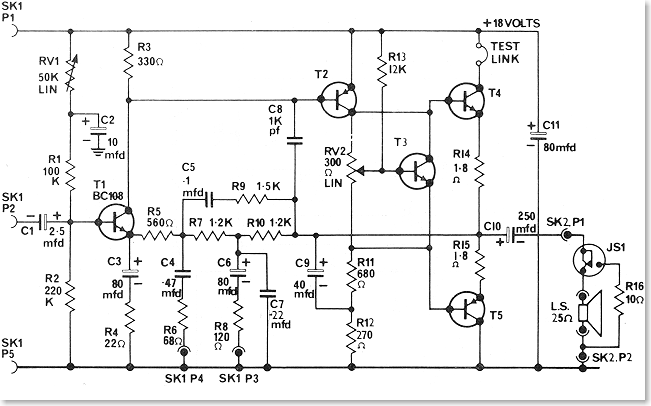
Transistor Radio Output Stages
The driver stage operates similarly to the previously described class A output stage, but it functions at a few milliamps, making efficiency less of a concern. The biasing configuration should be recognizable. Some circuits, including the one mentioned, incorporate an...
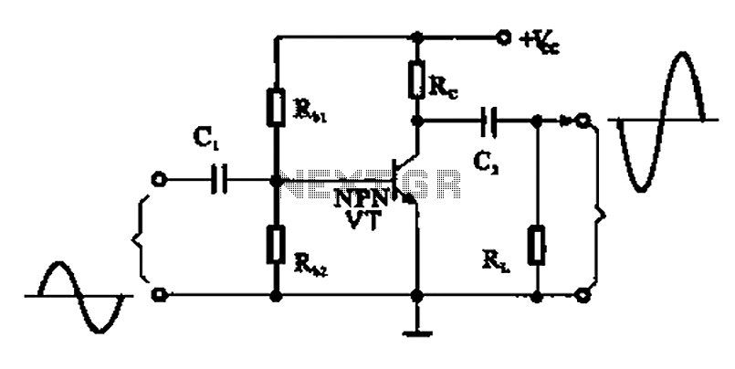
A common emitter amplifier
A common emitter amplifier is a total pole amplification circuit structure featuring a key emitting device. This circuit refers to the emitter of the input signal and the output signal connected to a common ground, forming the basis of fundamental...

Single Transistor Audio Mixer Circuit
This single transistor audio mixer is utilized in an amplifier circuit design featuring a base-driven transistor, with its emitter being current-controlled.
This audio mixer circuit employs a single transistor to facilitate the mixing of audio signals. The transistor operates in a...
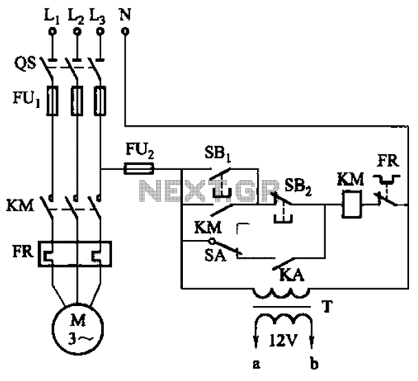
Six a start and stop intermittent cycle control circuits
The circuit illustrated in Figure 3-81 employs a transistor delay circuit to facilitate start-stop cycle control. It can operate in both manual and automatic modes. The circuit is primarily governed by the motor run time circuit, which includes transistors VTi...
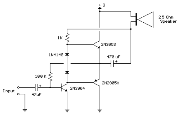
3 transistor audio amp 80 milliwatt
This circuit is similar to the previous one but employs positive feedback to enhance the amplitude delivered to the speaker. It was derived from a small 5-transistor radio utilizing a 25-ohm speaker. In the previous circuit, the load resistor for...
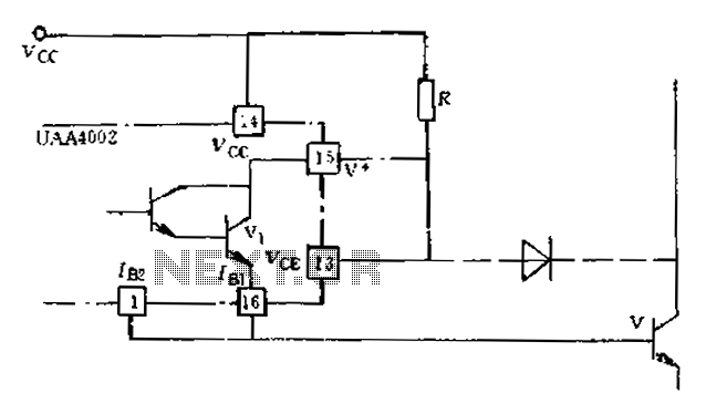
Anti-saturation function delete circuit schematics
Anti-saturation devices have been removed from the UAA4002 routine applications. The base current of the switching transistor, which is driven by another transistor, is automatically adjusted. This adjustment allows the power transistors to operate in critical saturation. However, when the...
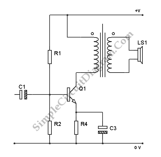
Transistor Class A Power Amplifier
The transistor is biased in Class A, meaning that the collector current flows continuously. This current can vary, increasing or decreasing in response to the input signal.
In a Class A biasing configuration, the transistor operates in the active region for...
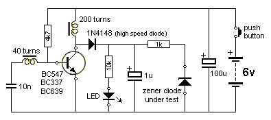
The Transistor Amplifier-P2
The three circuits described provide a constant current to the LED (or LEDs) when the supply voltage reaches 15V or higher. The second and third circuits can be activated or deactivated through the input line by turning on the top...

TRANSISTORIZED THYRATRON RING COUNTER
Each bistable circuit comprises two oppositely-symmetrical germanium transistors, two diodes, and four resistors. An additional transistor, Q, facilitates the transition of the conducting state to the next position when actuated by a transfer pulse. The absence of capacitors allows for...