


Car auto-dimmer
#auto-dimmer
#headlights
#light sensor
#hysteresis
#low beam
#directional detection
#car safety
#lens detector
#switching circuit
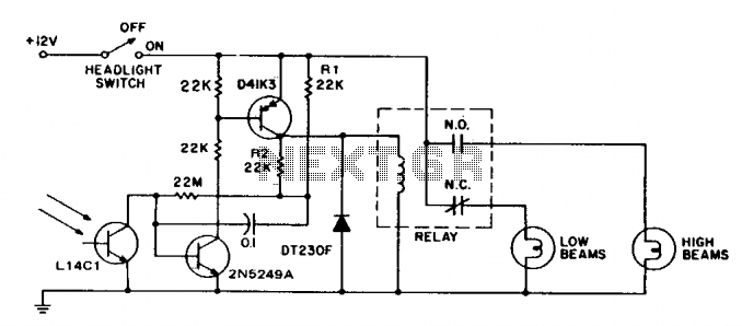
Description: This circuit switches car headlights to the low beam state when it detects the lights of an oncoming vehicle. The received light is of low intensity and highly directional, indicating the use of a lens with the detector. A significant amount of hysteresis is incorporated into the circuit to prevent the headlights from "flashing."
Sensitivity is adjusted by a 22 megohm resistor, setting it to approximately 0.5 foot-candle at the transistor (0.01 at the lens), while hysteresis is defined by the resistor voltage divider formed by R1 and R2, which is connected in parallel with the collector-emitter of the D41K3 transistor. This configuration drives the 22 megohm resistor. The maximum switching rate is restricted by a 0.1 µF capacitor to 15 operations per minute.
The relay used in the circuit operates at 12V with a coil current of 0.3A, and it can handle a maximum load of 20A with form C contacts or solid-state switching rated for 16A in steady-state conditions, with a cold filament surge rating of 160A. The lens employed has a minimum diameter of 1 inch and is positioned to provide an approximate 10-degree view angle.
This circuit effectively enhances vehicle safety by automatically dimming headlights in response to oncoming traffic, thereby reducing glare for other drivers. The light detection mechanism relies on a lens system that focuses light onto a sensitive phototransistor, which is calibrated to respond at low ambient light levels. The hysteresis feature is crucial in ensuring that the system does not react to transient light changes, such as those caused by streetlights or reflective surfaces, which could lead to unnecessary switching of the headlights.
The choice of a 22 megohm resistor for sensitivity adjustment allows for fine-tuning of the light detection threshold, ensuring optimal performance under varying environmental conditions. The voltage divider formed by R1 and R2 plays a vital role in establishing the required hysteresis, which helps maintain stable operation and prevents rapid cycling of the headlights.
The relay component serves as a robust switching mechanism, capable of handling substantial current loads, which is essential for automotive applications. The specification of a 12V relay is standard in vehicle electrical systems, and the ability to manage cold filament surges ensures that the circuit can withstand the inrush current experienced when headlights are first activated.
The lens design, with its minimum diameter and specified view angle, is critical for accurate light detection. The 10-degree view angle allows the sensor to effectively capture the headlights of oncoming vehicles while minimizing interference from other light sources. Overall, this circuit design exemplifies a practical approach to enhancing automotive lighting systems, promoting safer driving conditions through intelligent headlight management.This circuit switches car headlights to the low beam state when it senses the lights of an on-coming car. The received light is very low level and highly directional, indicating the use of a lens with the detector.
A relatively large amount of hysteresis is built into the circuit to prevent "flashing lights." Sensitivity is set by the 22 megohm resistor to about 0.5 ft. candle at the transistor (0.01 at the lens), while hysteresis is determined by the Rl, R2 resistor voltage divider, parallel to the D41K3 collector emitter, which drives the 22 megohm resistor; maximum switching rate is limited by the 0.1 ?Â¥ capacitor to 15/minute. relay: 12v, 0.3a coil: 20a, form c. contacts or solid-state switching of 16a steady-state 160a cold filament surge. rating. lens; minimum 1" diameter. positioned for about 10? view angle.
Sensitivity is adjusted by a 22 megohm resistor, setting it to approximately 0.5 foot-candle at the transistor (0.01 at the lens), while hysteresis is defined by the resistor voltage divider formed by R1 and R2, which is connected in parallel with the collector-emitter of the D41K3 transistor. This configuration drives the 22 megohm resistor. The maximum switching rate is restricted by a 0.1 µF capacitor to 15 operations per minute.
The relay used in the circuit operates at 12V with a coil current of 0.3A, and it can handle a maximum load of 20A with form C contacts or solid-state switching rated for 16A in steady-state conditions, with a cold filament surge rating of 160A. The lens employed has a minimum diameter of 1 inch and is positioned to provide an approximate 10-degree view angle.
This circuit effectively enhances vehicle safety by automatically dimming headlights in response to oncoming traffic, thereby reducing glare for other drivers. The light detection mechanism relies on a lens system that focuses light onto a sensitive phototransistor, which is calibrated to respond at low ambient light levels. The hysteresis feature is crucial in ensuring that the system does not react to transient light changes, such as those caused by streetlights or reflective surfaces, which could lead to unnecessary switching of the headlights.
The choice of a 22 megohm resistor for sensitivity adjustment allows for fine-tuning of the light detection threshold, ensuring optimal performance under varying environmental conditions. The voltage divider formed by R1 and R2 plays a vital role in establishing the required hysteresis, which helps maintain stable operation and prevents rapid cycling of the headlights.
The relay component serves as a robust switching mechanism, capable of handling substantial current loads, which is essential for automotive applications. The specification of a 12V relay is standard in vehicle electrical systems, and the ability to manage cold filament surges ensures that the circuit can withstand the inrush current experienced when headlights are first activated.
The lens design, with its minimum diameter and specified view angle, is critical for accurate light detection. The 10-degree view angle allows the sensor to effectively capture the headlights of oncoming vehicles while minimizing interference from other light sources. Overall, this circuit design exemplifies a practical approach to enhancing automotive lighting systems, promoting safer driving conditions through intelligent headlight management.This circuit switches car headlights to the low beam state when it senses the lights of an on-coming car. The received light is very low level and highly directional, indicating the use of a lens with the detector.
A relatively large amount of hysteresis is built into the circuit to prevent "flashing lights." Sensitivity is set by the 22 megohm resistor to about 0.5 ft. candle at the transistor (0.01 at the lens), while hysteresis is determined by the Rl, R2 resistor voltage divider, parallel to the D41K3 collector emitter, which drives the 22 megohm resistor; maximum switching rate is limited by the 0.1 ?Â¥ capacitor to 15/minute. relay: 12v, 0.3a coil: 20a, form c. contacts or solid-state switching of 16a steady-state 160a cold filament surge. rating. lens; minimum 1" diameter. positioned for about 10? view angle.
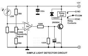
Light Sensor Circuit
An ambient light sensor circuit is a circuit that utilizes light intensity to perform various applications.
An ambient light sensor circuit typically consists of a light-dependent resistor (LDR) or phototransistor that detects the intensity of ambient light. The sensor converts the...
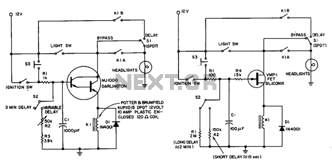
Delayed headlights circuit
This circuit maintains the headlights of an automobile in an on state temporarily. It also ensures that the lights turn off automatically, even if the user forgets to switch them off manually. The shut-off delay is activated only when both...
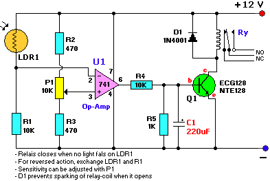
light dark sensor with relay circuit
The schematic diagram has been modified to include a 220µF smoothing capacitor connected between the base of transistor Q1 and ground. This addition effectively mitigated the issue of relay chatter, which involved rapid on/off switching at light levels. The incorporation...
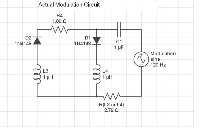
Parameter Variation Machines
Understanding the concept of hysteresis is crucial. Generally, this phenomenon leads to losses observed in the dielectric of a capacitor or the lamination of a transformer, which can manifest as heat (emission of infrared photons). Alternatively, it can extract work...
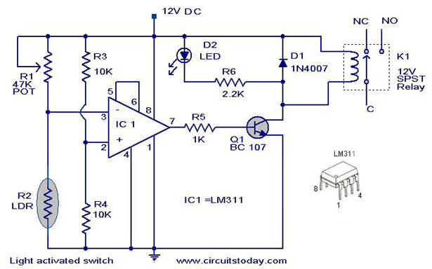
Light activated switch circuit
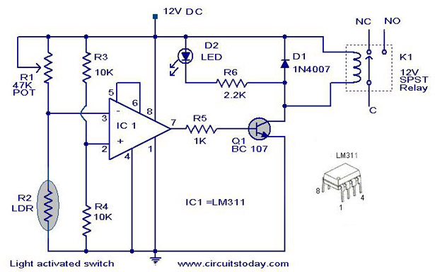
A simple light-activated switch circuit with a diagram and schematic using IC LM311 wired as a voltage comparator and an LDR that acts as a light sensor.
The described circuit utilizes the LM311 integrated circuit, which functions as a voltage comparator,...
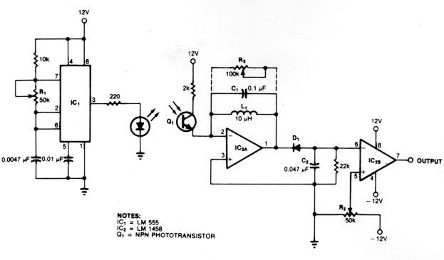
Light Sensor Circuits
Dark Activated Switch or Porch Light Switch. This circuit activates a relay when the light level drops below a preset threshold. The light sensitivity can be adjusted using variable resistor VR1, and the relay contacts can control an external light...
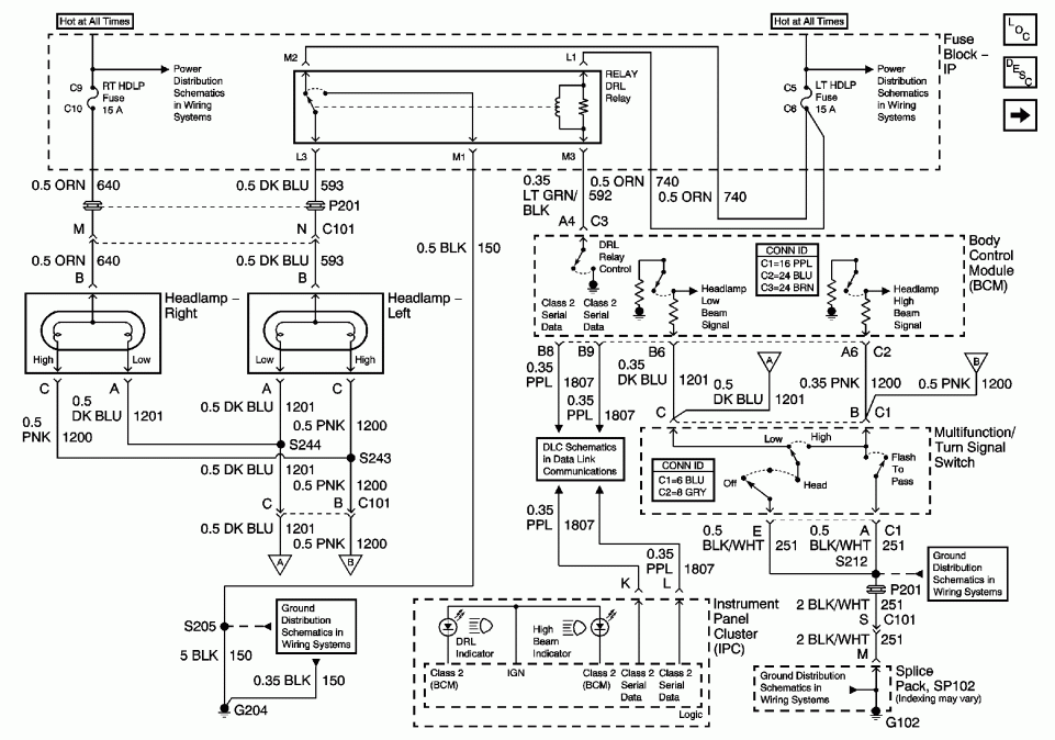
2001 cavalier: doesnt work daytime lights flash service light is on
A 2001 Chevrolet Cavalier has experienced a failure in one of the low beam headlights. Despite replacing the bulb, the headlight remains non-functional. Additionally, when the vehicle is shifted into gear, the daytime running lights flash multiple times before turning...
Most Popular Circuits
A simple light-activated switch circuit diagram utilizes the National Semiconductor comparator IC LM311 and a light-dependent resistor (LDR). The circuit functions as a voltage comparator, with the non-inverting input of IC1 receiving a reference voltage of 6V through resistors R3...
Low-light-level-drop-detector
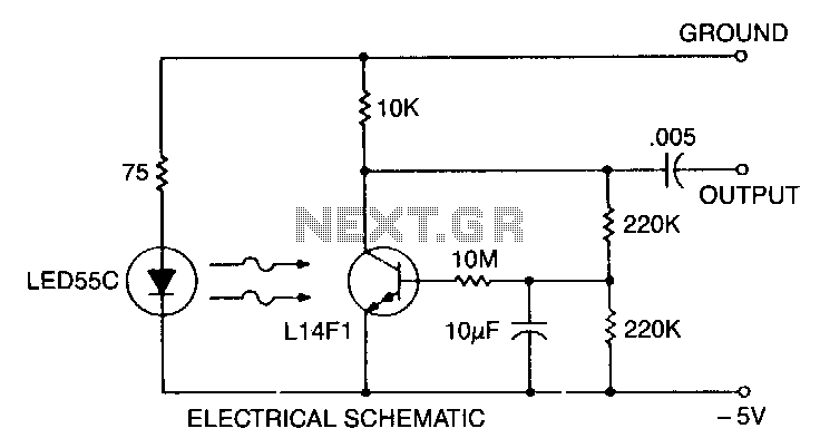
This self-biasing configuration is useful whenever small changes in light level must be detected, such as when monitoring very low flow rates by counting drops of fluid. In this bias method, the photodarlington is bias stabilized by feedback from the...