


Car battery monitor III
#battery monitor
#voltage drop
#LED indicator
#potentiometer
#starter
#defective battery
#automotive electronics
#battery health
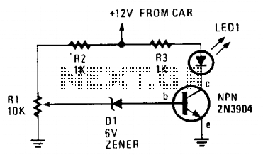
Description: The circuit is simple to assemble and install, and it notifies the user when the battery voltage drops below a predefined threshold set by R1, which is a 10,000-ohm potentiometer. It can signal through LED1 that the battery may be faulty or require replacement if operating the starter results in the battery voltage falling below the specified limit.
The circuit utilizes a basic voltage monitoring system that incorporates a 10,000-ohm potentiometer (R1) to establish the desired voltage threshold. When the battery voltage is above this threshold, the circuit remains inactive. However, if the voltage decreases below this level, the circuit activates LED1, providing a visual indication of a potential issue with the battery.
The 2N3904 transistor can be employed as a switching device in this configuration. When the voltage at the base of the transistor, controlled by the voltage divider formed by R1 and a reference resistor, falls below the set limit, the transistor turns on, allowing current to flow through LED1. This action illuminates the LED, alerting the user to the low battery condition.
In terms of assembly, the circuit requires minimal components: the potentiometer for voltage setting, the 2N3904 transistor, a current-limiting resistor for the LED, and the LED itself. The connections should be made carefully to ensure that the transistor is correctly oriented and that the LED is connected with the proper polarity to function effectively.
This circuit can be used in various applications where battery monitoring is essential, providing a straightforward and effective solution for ensuring battery health and reliability.The circuit is quick and easy to put together and install, and tells you when battery voltage falls below the set limit as established by Rl (a 10,000-ohm potentiometer). It can indicate, via LED 1, that the battery may be defective or in need of change if operating the starter causes the battery voltage to drop belciw the present limit.
You can use the 2N3904 or any equivalent.
The circuit utilizes a basic voltage monitoring system that incorporates a 10,000-ohm potentiometer (R1) to establish the desired voltage threshold. When the battery voltage is above this threshold, the circuit remains inactive. However, if the voltage decreases below this level, the circuit activates LED1, providing a visual indication of a potential issue with the battery.
The 2N3904 transistor can be employed as a switching device in this configuration. When the voltage at the base of the transistor, controlled by the voltage divider formed by R1 and a reference resistor, falls below the set limit, the transistor turns on, allowing current to flow through LED1. This action illuminates the LED, alerting the user to the low battery condition.
In terms of assembly, the circuit requires minimal components: the potentiometer for voltage setting, the 2N3904 transistor, a current-limiting resistor for the LED, and the LED itself. The connections should be made carefully to ensure that the transistor is correctly oriented and that the LED is connected with the proper polarity to function effectively.
This circuit can be used in various applications where battery monitoring is essential, providing a straightforward and effective solution for ensuring battery health and reliability.The circuit is quick and easy to put together and install, and tells you when battery voltage falls below the set limit as established by Rl (a 10,000-ohm potentiometer). It can indicate, via LED 1, that the battery may be defective or in need of change if operating the starter causes the battery voltage to drop belciw the present limit.
You can use the 2N3904 or any equivalent.
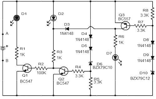
Car battery monitor circuit diagram
When the battery voltage is 11.5V or less, transistor Q1 is activated, and LED D1 will illuminate. When the battery voltage is between 11.5V and 13.5V, transistor Q2 is activated, causing LED D2 to light up. At a battery voltage...
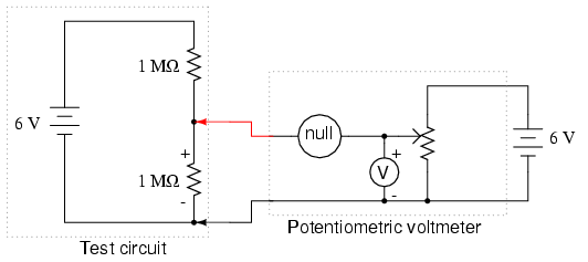
Potentiometric voltmeter
The potentiometer value is not critical; any value from 1 kΩ to 100 kΩ is acceptable. If the "precision potentiometer" described earlier in this chapter has been constructed, it is recommended for use in this experiment. The actual values of...

Battery Voltage monitor
Battery voltage monitor is utilized to indicate the voltage level of a 12-volt battery circuit, specifically in a verified electronics project circuit.
The battery voltage monitor circuit is designed to provide a visual representation of the voltage level of a 12-volt...
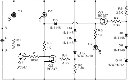
car battery monitor with 3 led
When the battery voltage is 11.5V or lower, transistor Q1 is activated, causing LED D1 to illuminate. If the battery voltage is between 11.5V and 13.5V, transistor Q2 is activated, resulting in LED D2 lighting up. At a battery voltage...
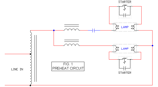
Preheat Ballast Schematic
It includes a starter for each lamp that heats the filaments (cathodes) at both ends of the lamp before ignition. Once the lamp is lit, the heated filaments are no longer necessary. The heating serves solely as an ignition aid....

Car Battery Alarm
To check the battery in a car, an easy circuit utilizing the IC CA3140 and a transistor is employed. The voltage level of an automobile battery is influenced by many factors, and if it is high...
The circuit for checking a...
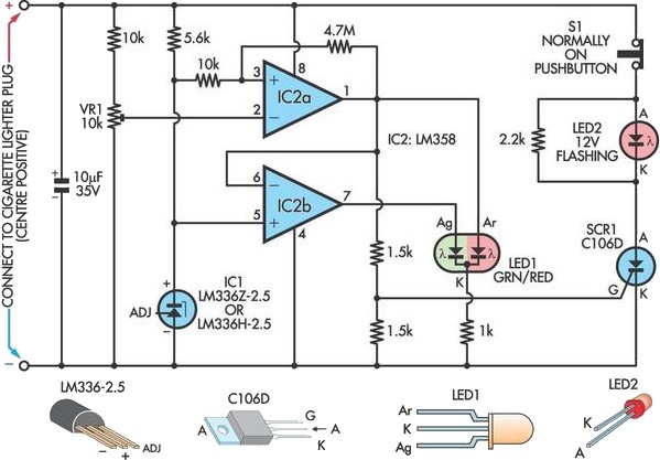
Car Battery Failure Detector
A car battery deteriorates with use, typically lasting no more than four years. Initially, its voltage may drop to just 2V when cranking the engine. As the battery ages, its internal impedance increases, leading to a higher voltage drop during...
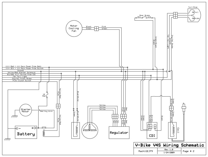
help diagnose stator
A 2005 Wildfire 250 QAC ATV is experiencing starting issues. When attempting to start, it sounds as though the starter gears are spinning without engaging. After flipping the ATV, the problem has persisted. There is a one-way clutch between the...
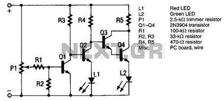
Car Battery And Alternator Monitor Circuit
The monitor functions as a basic voltage comparator, utilizing a car battery as its power source. The input voltage to the comparator is adjusted using potentiometer PI. This adjustment ensures that the green LED L2 illuminates when the alternator is...