


Car tv cronograph
#car TV
#cronograph
#semaphore lights
#sound effects
#jump start indicator
#timing display
#automotive electronics
#TV interface
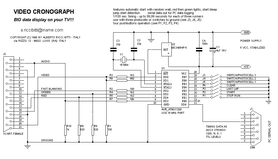
Description: This design is based on the video DVM design. Furthermore, it adds support for color, so you will get red and green semaphore lights (as those in formula 1) and sound: you will even hear the starting-horn sound! Up to 3 times are displayed on YOUR TV screen. When you press the START button, the red semaphores will light on, and, after a random delay, the unit activates the green ones emitting a bleep sound. If one of the runners starts in advance, a jump start (F= false start) indicator is displayed. Timers increment with 1/100 resolution until last lap, when they are stopped by the photocells. Maximum race time is 99".99. Even checkerboard flags will appear near the times when each runner comes to end! At the race end, times are transmitted through the serial interface as ASCII strings at 1200 baud. Although, computer is NOT necessary as the same information is displayed on TV screen. Times are triggered by photocells, that can be replaced by any other mechanical or electronic switch, so you can time any other short event (up to three timers at once). "START" fires the red semaphores. Random time, then lights turns to green and time runs. Here the 3rd car made a jump start, making the race void. Time runs. The arrows mean "other laps" to end. Photocells are inhibited until the judge presses the "LAST LAP" key. As cars reach the finish line, time stops and the checkerboard flag appears. Here the 3rd car won, followed by 1st. The second car is still running. All is done using only a 512 lines assembler program, showing well the compactness of the Atmel's AVR AT90S1200 code.
The electronic circuit design described features a sophisticated timing and signaling system suitable for racing events. The core of the system is based on a digital video multimeter (DVM) design, enhanced with color semaphore lights and audio cues to simulate a real racing environment.
The circuit utilizes red and green LED semaphore lights to indicate race statuses. The red lights activate upon pressing the START button, signaling the beginning of the race. After a random delay, the green lights illuminate, indicating that the race is underway, accompanied by a sound module that emits a starting horn. This sound is generated using a small audio amplifier connected to a piezo speaker or similar output device.
The timing mechanism is capable of measuring up to three participants simultaneously, with timers incrementing at a resolution of 1/100 seconds. The timers are controlled by a microcontroller, specifically the Atmel AVR AT90S1200, programmed in a compact 512-line assembler code. This microcontroller interfaces with photocells placed at the start and finish lines to accurately capture the timing of each runner. The maximum race duration is capped at 99.99 seconds, which is displayed on a connected television screen.
When a runner crosses the start line prematurely, a jump start indicator is activated, notifying the user of a false start. The circuit also includes functionality to display a checkerboard flag when each participant finishes the race, providing a visual cue for the end of their timing.
At the end of the race, the recorded times are transmitted via a serial interface at 1200 baud as ASCII strings. This transmission allows for easy logging or further processing if connected to a computer, although the system is designed to function independently with the TV display. The photocells can be replaced with mechanical or electronic switches, allowing flexibility to time various short events beyond racing.
The system also incorporates a "LAST LAP" key, which temporarily inhibits the photocells until pressed by a judge, ensuring that the timing for the final lap is accurately recorded. This feature enhances the reliability of the timing system during competitive events.
Overall, the design integrates various electronic components including LEDs, an audio module, a microcontroller, and photocells to create a comprehensive race timing and signaling solution. This design is based on the video DVM design. Furthermore, it adds support for color, so you will get red and green semaphore lights (as those in formula 1) and sound: you will even hear the starting-horn sound! Up to 3 times are displayed on YOUR TV screen. When you press the START button, the red semaphores will light on, and, after a random delay, the unit activates the green ones emitting a bleep sound.
If one of the runners starts in advance, a jump start (F= false start) indicator is displayed. Timers increment with 1/100 resolution until last lap, when they are stopped by the photocells. Maximum race time is 99".99. Even chekerboard flags will appear near the times when each runner comes to end! At the race end, times are transmitted through the serial interface as ASCII strings at 1200 baud. Altough, computer is NOT necessary as the same information is displayed on TV screen. Times are triggered by photocells, that can be replaced by any other mechanical or electronic switch, so you can time any other short event (up to three timers at once). "START" fires the red semaphores. Random time, then lights turns to green and time runs. Here the 3rd car made a jump start, making the race void. Time runs. The arrows mean "other laps" to end. Photocells are inhibited until the judge presses the "LAST LAP" key. As cars reach the finish line, time stops and the checkerboard flag appear. Here the 3rd car won, followed by 1st. The second car is still running. All is done using only a 512 lines assembler program, showing well the compactness of the Atmel's AVR AT90S1200 code.
The electronic circuit design described features a sophisticated timing and signaling system suitable for racing events. The core of the system is based on a digital video multimeter (DVM) design, enhanced with color semaphore lights and audio cues to simulate a real racing environment.
The circuit utilizes red and green LED semaphore lights to indicate race statuses. The red lights activate upon pressing the START button, signaling the beginning of the race. After a random delay, the green lights illuminate, indicating that the race is underway, accompanied by a sound module that emits a starting horn. This sound is generated using a small audio amplifier connected to a piezo speaker or similar output device.
The timing mechanism is capable of measuring up to three participants simultaneously, with timers incrementing at a resolution of 1/100 seconds. The timers are controlled by a microcontroller, specifically the Atmel AVR AT90S1200, programmed in a compact 512-line assembler code. This microcontroller interfaces with photocells placed at the start and finish lines to accurately capture the timing of each runner. The maximum race duration is capped at 99.99 seconds, which is displayed on a connected television screen.
When a runner crosses the start line prematurely, a jump start indicator is activated, notifying the user of a false start. The circuit also includes functionality to display a checkerboard flag when each participant finishes the race, providing a visual cue for the end of their timing.
At the end of the race, the recorded times are transmitted via a serial interface at 1200 baud as ASCII strings. This transmission allows for easy logging or further processing if connected to a computer, although the system is designed to function independently with the TV display. The photocells can be replaced with mechanical or electronic switches, allowing flexibility to time various short events beyond racing.
The system also incorporates a "LAST LAP" key, which temporarily inhibits the photocells until pressed by a judge, ensuring that the timing for the final lap is accurately recorded. This feature enhances the reliability of the timing system during competitive events.
Overall, the design integrates various electronic components including LEDs, an audio module, a microcontroller, and photocells to create a comprehensive race timing and signaling solution. This design is based on the video DVM design. Furthermore, it adds support for color, so you will get red and green semaphore lights (as those in formula 1) and sound: you will even hear the starting-horn sound! Up to 3 times are displayed on YOUR TV screen. When you press the START button, the red semaphores will light on, and, after a random delay, the unit activates the green ones emitting a bleep sound.
If one of the runners starts in advance, a jump start (F= false start) indicator is displayed. Timers increment with 1/100 resolution until last lap, when they are stopped by the photocells. Maximum race time is 99".99. Even chekerboard flags will appear near the times when each runner comes to end! At the race end, times are transmitted through the serial interface as ASCII strings at 1200 baud. Altough, computer is NOT necessary as the same information is displayed on TV screen. Times are triggered by photocells, that can be replaced by any other mechanical or electronic switch, so you can time any other short event (up to three timers at once). "START" fires the red semaphores. Random time, then lights turns to green and time runs. Here the 3rd car made a jump start, making the race void. Time runs. The arrows mean "other laps" to end. Photocells are inhibited until the judge presses the "LAST LAP" key. As cars reach the finish line, time stops and the checkerboard flag appear. Here the 3rd car won, followed by 1st. The second car is still running. All is done using only a 512 lines assembler program, showing well the compactness of the Atmel's AVR AT90S1200 code.
Rain Sound Effects Generator
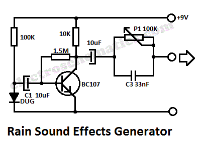
This rain sound effects generator circuit simulates the sound of rain and can be utilized in electronic music and radio shows. The noise source employs a germanium diode that is directly polarized and subsequently amplified by a single-stage amplifier to...
Sound Effects Generator 2
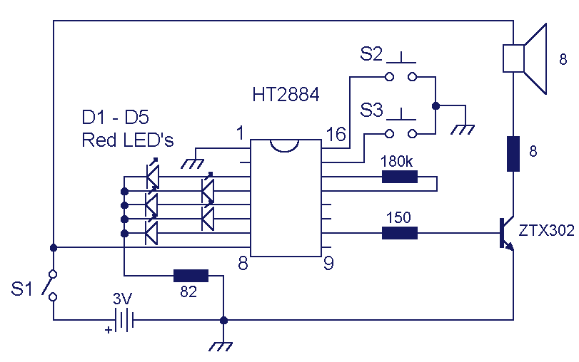
This circuit uses the Holtek HT2884 IC to produce 8 different sound effects. All sound effects are generated internally by the HT2884 IC. Power is a 3 Volt battery, but the IC will work with any voltage between 2.5 and...
Sound Effects Generators
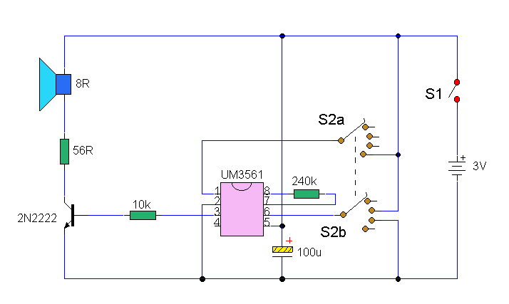
The integrated circuit (IC) generates various sound effects, with the output at Pin 3 amplified by a transistor. A 64-ohm loudspeaker can replace the 56-ohm resistor and 8-ohm loudspeaker. A two-pole, four-way switch controls the sound effects, with position 1...
Sound-effects-generator
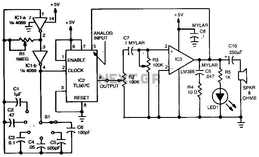
A variable dock-pulse generator consists of two sections of IC1, which is a 4069 CMOS hex inverter, along with resistor R1, switch S1, and capacitors C1 through C6. By adjusting R1 and switching one of the capacitors into the circuit,...
Sound Effects Kits
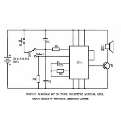
The core of the circuit is an IC4822, referred to as IC1. The IC4822 is a programmed ROM that produces 16 musical tunes upon being triggered. Its main features include an integrated tone generator, rhythm generator, modulator, oscillator, frequency divider,...
Sound effects generator
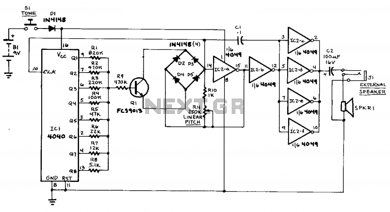
This circuit can generate sounds such as a European police-car siren, bird noises, and spaceship sounds. It can also function as a doorbell or an alarm. The circuit consists of four main components: a binary counter, a digital-to-analog (D/A) converter,...
Echo Bender V2
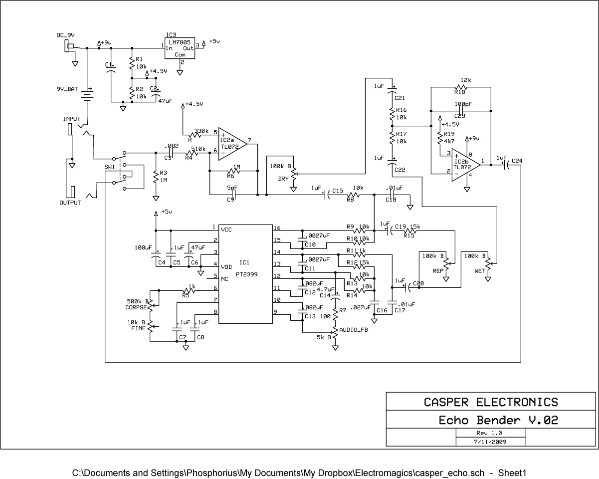
A significant aspect of the soundscape effect appears to stem from adjusting the potentiometers while playing. A request has been made for a version that utilizes slide resistors instead of potentiometers, mounted on foot pedals for real-time manipulation during performance....
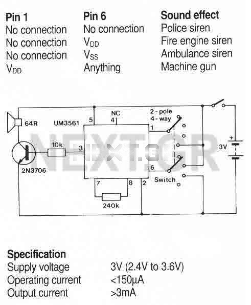
Sound effects generator (UM3561)
A simple sound generator IC that can produce four sound effects. Designed for use in toys, the effects are selected by varying the connections to pins 1 and 6 as follows. More: A usual toy sounder IC circuit.
The sound generator...
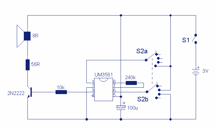
Sound Effects Generator
This circuit uses a UM3561 IC to produce four different sound effects. Nothing too complicated here. The IC produces all the sound effects, the output at Pin 3 being amplified by the transistor. A 64 ohm loudspeaker can be substituted...