


Car Wiper Controller
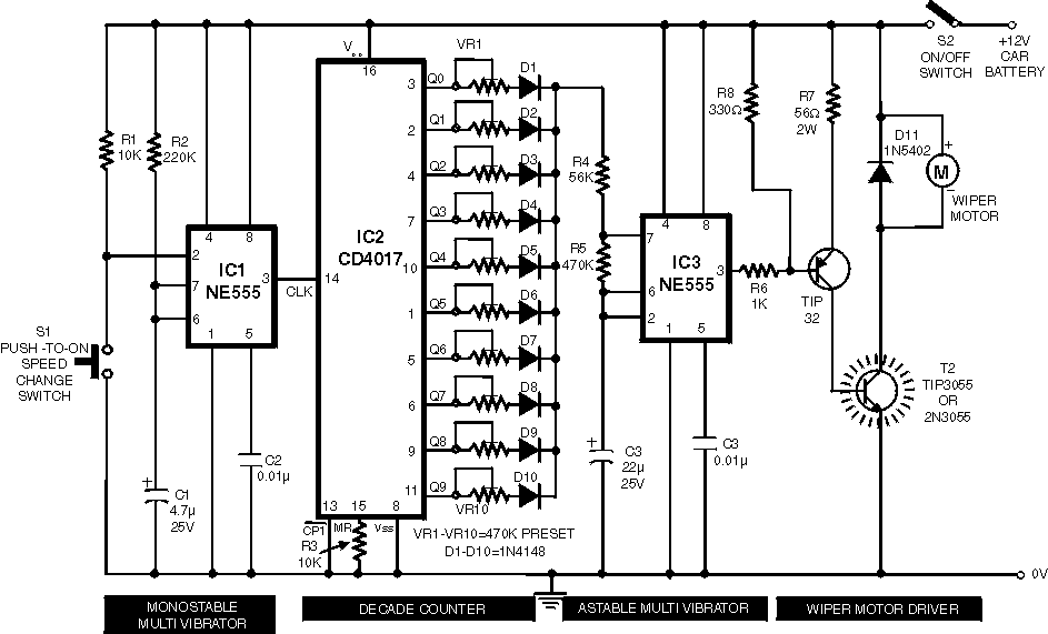
Description: A continuously working wiper in a car may prove to be a nuisance, especially when it is not raining heavily. By using the circuit described here one can vary the sweeping rate of the wiper from once a second to once in ten seconds. The circuit comprises two timer NE555 ICs, one CD4017 decade counter, one TIP32 driver transistor, a 2N3055 power transistor (or TIP3055) and a few other discrete components. Timer IC1 is configured as a monostable multivibrator which produces a pulse when one presses switch S1 momentarily. This pulse acts as a clock pulse for the decade counter (IC2) which advances by one count on each successive clock pulse or the push of switch S1. Ten presets (VR1 through VR10), set for different values by trial and error, are used at the ten outputs of IC2. But since only one output of IC2 is high at a time, only one preset (at selected output) effectively comes in series with timing resistors R4 and R5 connected in the circuit of timer IC3 which functions in astable mode. As presets VR1 through VR10 are set for different values, different time periods (or frequencies) for astable multivibrator IC3 can be selected. The output of IC3 is applied to pnp driver transistor T1 (TIP32) for driving the final power transistor T2 (2N3055) which in turn drives the wiper motor at the selected sweep speed. The power supply for the wiper motor as well as the circuit is tapped from the vehicle's battery itself. The duration of monostable multivibrator IC1 is set for a nearly one second period.
The circuit operates by utilizing two NE555 timer ICs, where IC1 is configured in a monostable mode to generate a single pulse when activated by switch S1. This pulse serves as a clock signal for the CD4017 decade counter (IC2), enabling it to progress through its ten outputs sequentially with each press of S1. The configuration allows for a variable wiper speed, as the outputs of IC2 are connected to ten variable resistors (VR1 to VR10), each preset to different resistance values to achieve distinct timing intervals.
The selected output from IC2 is connected in series with resistors R4 and R5, which are part of the timing circuit for the second NE555 timer (IC3) operating in astable mode. The astable configuration of IC3 allows it to generate a continuous square wave signal, with the frequency of oscillation determined by the selected preset resistor value. This frequency corresponds to the desired wiper sweep speed, varying from once every second to once every ten seconds depending on the position of the selected preset.
The output from IC3 drives a PNP transistor (TIP32), which acts as a switching device to control the larger power transistor (2N3055). The power transistor is responsible for supplying the necessary current to the wiper motor, thereby controlling its operation based on the frequency provided by the astable multivibrator. The entire circuit is powered by the vehicle's battery, ensuring that the wiper system operates efficiently within the automotive environment. The design allows for a practical solution to manage wiper operation, enhancing user convenience and improving visibility during varying weather conditions.A continuously working wiper in a car may prove to be a nuisance, especially when it is not raining heavily. By using the circuit described here one can vary sweeping rate of the wiper from once a second to once in ten seconds.
The circuit comprises two timer NE555 ICs, one CD4017 decade counter, one TIP32 driver transistor, a 2N3055 power transistor (or TIP3055) and a few other discrete components. Timer IC1 is configured as a mono- stable multivibrator which produces a pulse when one presses switch S1 momentarily.
This pulse acts as a clock pulse for the decade counter (IC2) which advances by one count on each successive clock pulse or the push of switch S1. Ten presets (VR1 through VR10), set for different values by trial and error, are used at the ten outputs of IC2.
But since only one output of IC2 is high at a time, only one preset (at selected output) effectively comes in series with timing resistors R4 and R5 connected in the circuit of timer IC3 which functions in astable mode. As presets VR1 through VR10 are set for different values, different time periods (or frequencies) for astable multivibrator IC3 can be selected.
The output of IC3 is applied to pnp driver transistor T1 (TIP32) for driving the final power transistor T2 (2N3055) which in turn drives the wiper motor at the selected sweep speed. The power supply for the wiper motor as well as the circuit is tapped from the vehicles battery itself.
The duration of monostable multivibrator IC1 is set for a nearly one second period.
The circuit operates by utilizing two NE555 timer ICs, where IC1 is configured in a monostable mode to generate a single pulse when activated by switch S1. This pulse serves as a clock signal for the CD4017 decade counter (IC2), enabling it to progress through its ten outputs sequentially with each press of S1. The configuration allows for a variable wiper speed, as the outputs of IC2 are connected to ten variable resistors (VR1 to VR10), each preset to different resistance values to achieve distinct timing intervals.
The selected output from IC2 is connected in series with resistors R4 and R5, which are part of the timing circuit for the second NE555 timer (IC3) operating in astable mode. The astable configuration of IC3 allows it to generate a continuous square wave signal, with the frequency of oscillation determined by the selected preset resistor value. This frequency corresponds to the desired wiper sweep speed, varying from once every second to once every ten seconds depending on the position of the selected preset.
The output from IC3 drives a PNP transistor (TIP32), which acts as a switching device to control the larger power transistor (2N3055). The power transistor is responsible for supplying the necessary current to the wiper motor, thereby controlling its operation based on the frequency provided by the astable multivibrator. The entire circuit is powered by the vehicle's battery, ensuring that the wiper system operates efficiently within the automotive environment. The design allows for a practical solution to manage wiper operation, enhancing user convenience and improving visibility during varying weather conditions.A continuously working wiper in a car may prove to be a nuisance, especially when it is not raining heavily. By using the circuit described here one can vary sweeping rate of the wiper from once a second to once in ten seconds.
The circuit comprises two timer NE555 ICs, one CD4017 decade counter, one TIP32 driver transistor, a 2N3055 power transistor (or TIP3055) and a few other discrete components. Timer IC1 is configured as a mono- stable multivibrator which produces a pulse when one presses switch S1 momentarily.
This pulse acts as a clock pulse for the decade counter (IC2) which advances by one count on each successive clock pulse or the push of switch S1. Ten presets (VR1 through VR10), set for different values by trial and error, are used at the ten outputs of IC2.
But since only one output of IC2 is high at a time, only one preset (at selected output) effectively comes in series with timing resistors R4 and R5 connected in the circuit of timer IC3 which functions in astable mode. As presets VR1 through VR10 are set for different values, different time periods (or frequencies) for astable multivibrator IC3 can be selected.
The output of IC3 is applied to pnp driver transistor T1 (TIP32) for driving the final power transistor T2 (2N3055) which in turn drives the wiper motor at the selected sweep speed. The power supply for the wiper motor as well as the circuit is tapped from the vehicles battery itself.
The duration of monostable multivibrator IC1 is set for a nearly one second period.
10 Step Baby Gate Sequencer CD4017
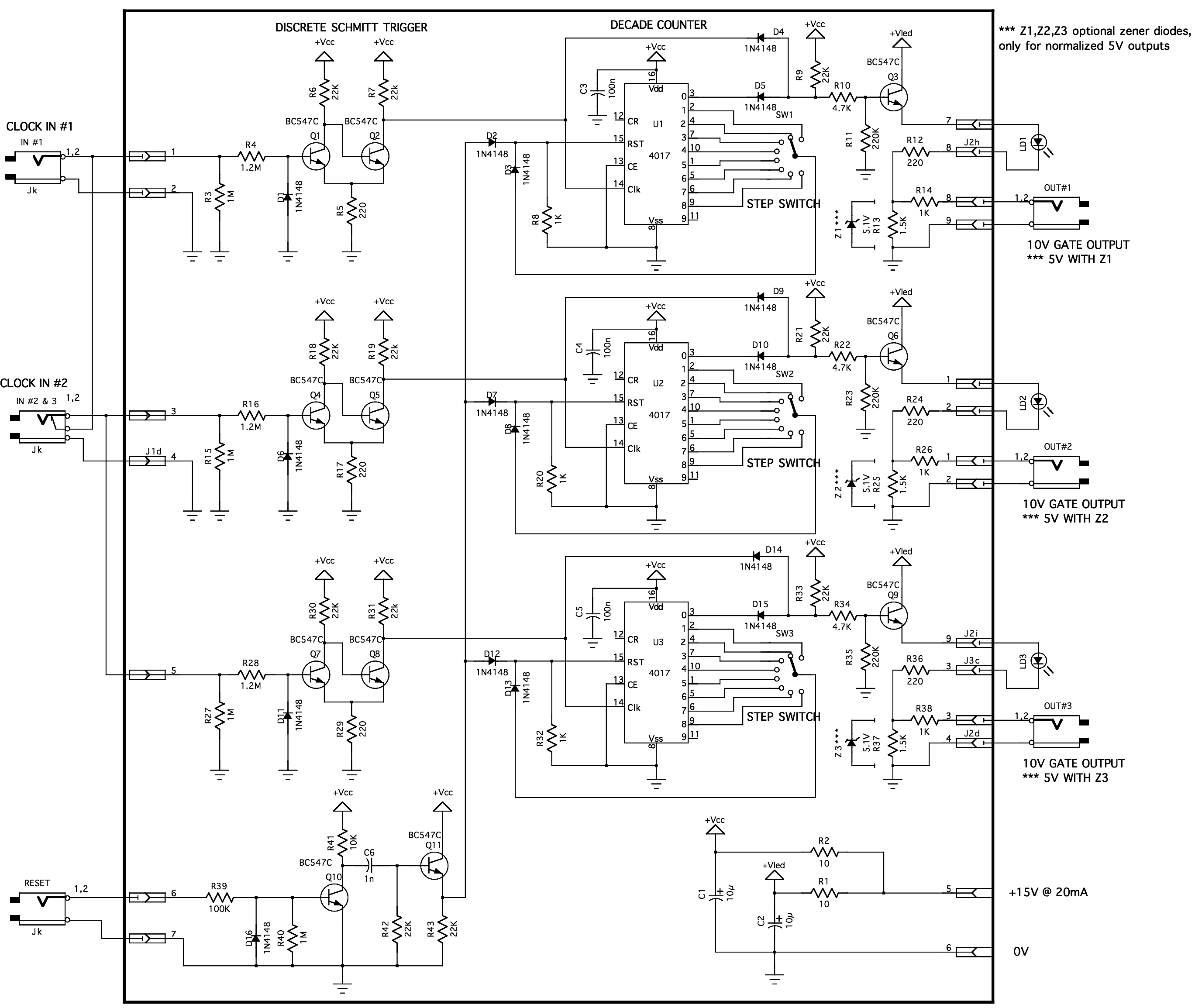
The latest version of the "baby 10 sequencer" has been completed, featuring control voltage and gate switches. Some issues were encountered with the module, and modifications are planned for the near future. In preparation for enhancing the baby 10 sequencer,...
Voltage doubler circuit using NE555
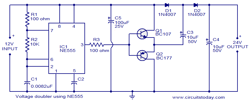
The circuit diagram of a simple voltage doubler using the NE555 timer is presented. In this configuration, the NE555 IC operates as an astable multivibrator at approximately 9 kHz. The bases of two transistors, Q1 and Q2, are connected together,...
Intermittent start and stop cycle control circuit Five of a
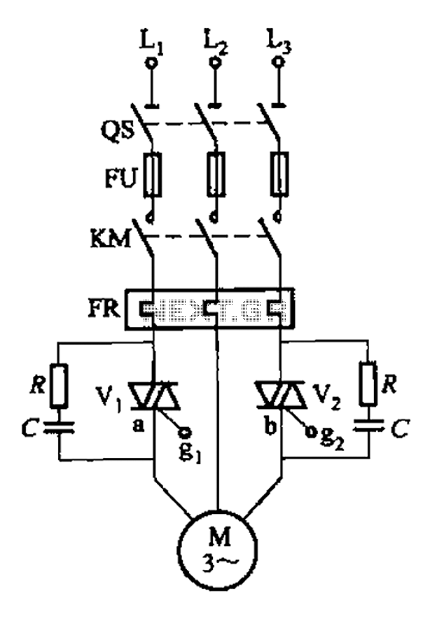
The circuit depicted in Figure 3-80 is responsible for controlling a portion of the transistor multivibrator. A multivibrator serves as a robust positive and negative feed-forward amplifier, consisting of two branches that are interconnected through a coupled RC timing circuit,...
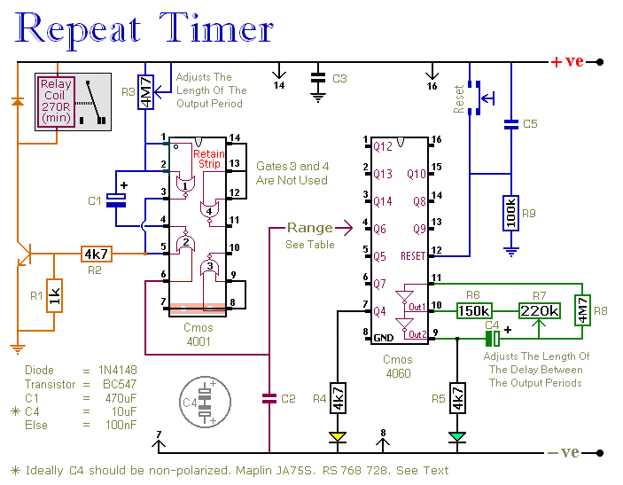
Repeating Interval Timer circuit
This circuit features an adjustable output timer capable of re-triggering at specified intervals. The output duration can range from a fraction of a second to over half an hour, with the ability to recur at regular intervals spanning from seconds...
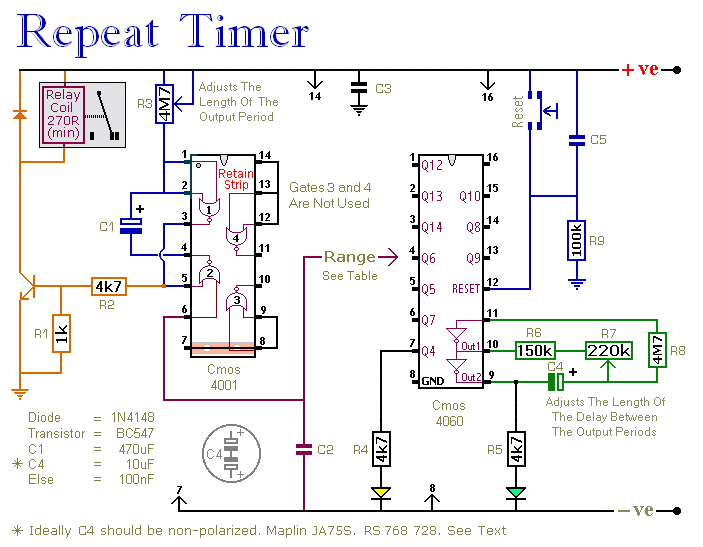
A Regularly Repeating Interval Timer circuit
This circuit features an adjustable output timer capable of re-triggering at regular intervals. The output duration can range from a fraction of a second to over half an hour, and it can be configured to recur at regular intervals from...
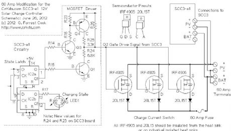
Digitally controlled threshold detector
This circuit utilizes small switching transistors, with a maximum motor drive current limited to approximately 250 mA at 5V. Testing has been conducted across a voltage range from 3V to 21V, and with certain component modifications, it may be applicable...
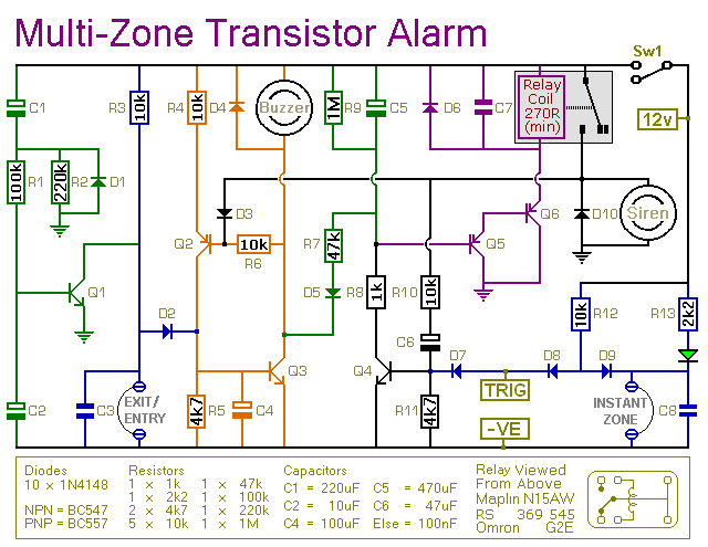
expandable transistor based burglar alarm
This transistor-based alarm system incorporates automatic exit and entry delays, along with a timed bell cut-off and system reset functionality. In addition to the exit/entry zone, the fundamental alarm board includes one instant zone, which is sufficient for many applications....
1kHz square wave signal generator
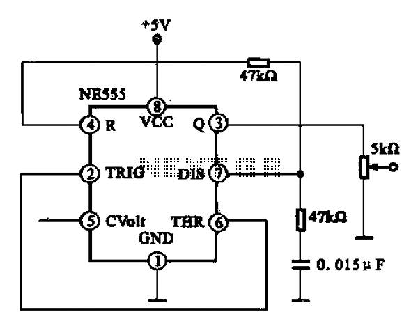
A 1 kHz square wave signal generator is created using a time base circuit with an NE555 timer, combined with a time constant circuit consisting of a 47 kΩ resistor and a 0.15 µF capacitor.
The circuit utilizes the NE555...
2 Transistor LED Flasher
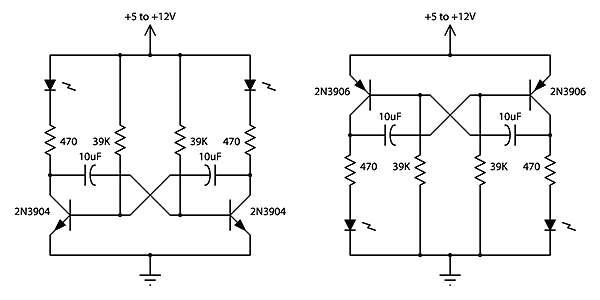
This is a classic 2-transistor astable multivibrator. Many other NPN small signal or switching transistors can be used, including 2N4401, PN2222, or 2N2222 using the circuit on the left. The circuit can also be inverted using PNP transistors such as...