


Daewoo Korando Front and Rear Fog Lamp Schematic and Routing Diagrams
#fog lamp
#wiring diagram
#Daewoo Korando
#ignition switch
#relay
#multifunction switch
#automotive lighting
#vehicle electronics
#electrical schematic
#front and rear fog lamps
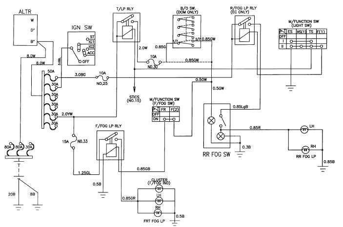
Description: The schematic for the front and rear fog lamps of the Daewoo Korando is illustrated in the accompanying figure. It details the connections and wiring between various components of the fog lamp system, including the alternator, ignition switch, taillamp relay, b/0 switch, rear fog lamp relay, multifunction switch, front fog lamp relay, rear fog switch, cluster, and additional elements.
The fog lamp system in the Daewoo Korando is designed to enhance visibility during adverse weather conditions. The schematic displays a comprehensive layout of the electrical connections required for the operation of both front and rear fog lamps.
The alternator serves as the primary power source, supplying voltage to the entire lighting system. The ignition switch is crucial for activating the fog lamps, ensuring that they only operate when the vehicle is in an "on" state. The taillamp relay is included in the circuit to manage the power distribution to the taillights, which may be integrated with the fog lamp system for enhanced visibility.
The b/0 switch functions as a safety mechanism, preventing the fog lamps from being activated when not required. The rear fog lamp relay is responsible for controlling the rear fog lights, allowing them to be turned on or off independently from the front fog lamps. The multifunction switch is an essential component that enables the driver to control various lighting functions, including the fog lamps, from a single interface.
The front fog lamp relay is dedicated to the operation of the front fog lights, ensuring they receive the correct voltage and current for optimal performance. The rear fog switch allows the driver to activate the rear fog lamps, providing additional safety during low visibility conditions. The cluster may include indicators that inform the driver when the fog lamps are active, contributing to an overall safer driving experience.
This schematic is an essential reference for technicians and engineers involved in the maintenance and troubleshooting of the fog lamp system in the Daewoo Korando, ensuring that all components work together effectively to provide enhanced visibility and safety on the road.Front and rear fog lamp schematic of Daewoo Korando shown in the following figure. It shows the connection and wiring between each parts and component of front and rear fog lamp system of the vehicle such as alternator, ignition switch, taillamp relay, b/0 switch, rear fog lamp relay, multifunction switch, front fog lamp relay, rear fog switch, cl uster, and many others. Herein is the schematic :
The fog lamp system in the Daewoo Korando is designed to enhance visibility during adverse weather conditions. The schematic displays a comprehensive layout of the electrical connections required for the operation of both front and rear fog lamps.
The alternator serves as the primary power source, supplying voltage to the entire lighting system. The ignition switch is crucial for activating the fog lamps, ensuring that they only operate when the vehicle is in an "on" state. The taillamp relay is included in the circuit to manage the power distribution to the taillights, which may be integrated with the fog lamp system for enhanced visibility.
The b/0 switch functions as a safety mechanism, preventing the fog lamps from being activated when not required. The rear fog lamp relay is responsible for controlling the rear fog lights, allowing them to be turned on or off independently from the front fog lamps. The multifunction switch is an essential component that enables the driver to control various lighting functions, including the fog lamps, from a single interface.
The front fog lamp relay is dedicated to the operation of the front fog lights, ensuring they receive the correct voltage and current for optimal performance. The rear fog switch allows the driver to activate the rear fog lamps, providing additional safety during low visibility conditions. The cluster may include indicators that inform the driver when the fog lamps are active, contributing to an overall safer driving experience.
This schematic is an essential reference for technicians and engineers involved in the maintenance and troubleshooting of the fog lamp system in the Daewoo Korando, ensuring that all components work together effectively to provide enhanced visibility and safety on the road.Front and rear fog lamp schematic of Daewoo Korando shown in the following figure. It shows the connection and wiring between each parts and component of front and rear fog lamp system of the vehicle such as alternator, ignition switch, taillamp relay, b/0 switch, rear fog lamp relay, multifunction switch, front fog lamp relay, rear fog switch, cl uster, and many others. Herein is the schematic :
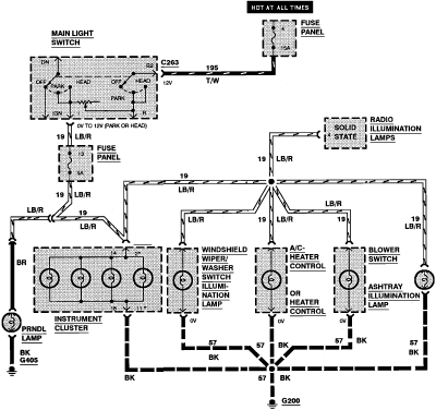
1994 Mercury Topaz Instrument Cluster Illumination Wiring Diagram
1994 Mercury Topaz Instrument Cluster Illumination Wiring Diagram.
The 1994 Mercury Topaz instrument cluster illumination wiring diagram provides a detailed representation of the electrical connections and components responsible for the lighting system within the instrument panel. This diagram is essential for...
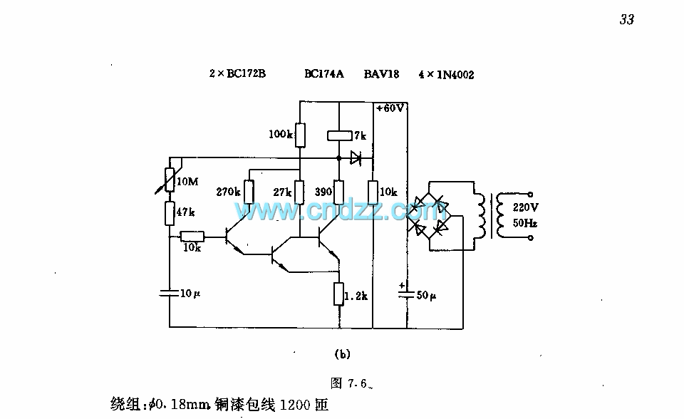
Relay pull-in timer circuit in time process
The circuit features a two-stage structure with a timing range of approximately 0.5 to 12 seconds, while in a specified configuration, the timing range extends from 1 to 160 seconds. The transformer parameters include an iron core made of M42/15.7...
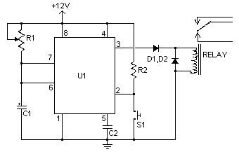
time delay relay
A time delay relay is a relay that remains activated for a specific duration after being triggered. This type of relay consists of a straightforward adjustable timer circuit that regulates the operation of the relay. The timing can be adjusted...
Universal Power Controller
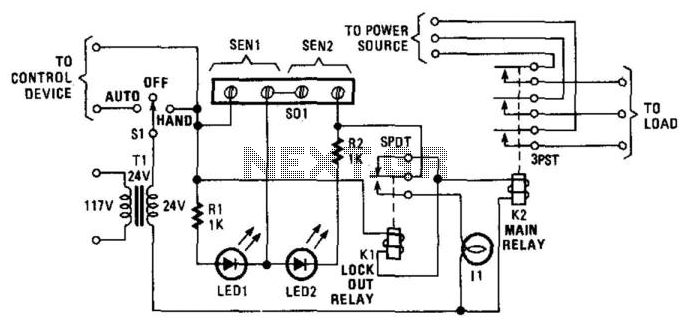
Relay K1 features a low-impedance coil, while Relay K2 is equipped with a high-impedance coil. When a sensor opens, current flows through the coil of K1, activating it. This action opens the contacts of K1, thereby preventing the reclosure of...
microcontroller 12V relay circuit converted to 5V relay under uC control
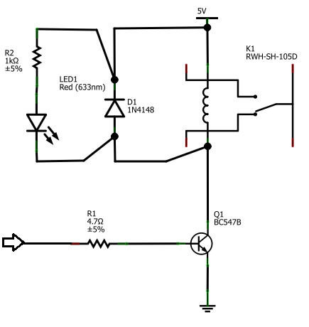
The BC547B transistor has a collector-base voltage (Vcbo) of 50V, a collector-emitter voltage (Vceo) of 45V, and an emitter-base voltage (Vebo) of 6V. In contrast, the BC548 transistor in the original circuit has a Vcbo of 30V, a Vceo of...
Wiring Diagram and Electrical Circuit Troubleshooting Of 1997 Chevrolet Blazer
The following circuit illustrates the wiring diagram and electrical circuit troubleshooting for the 1997 Chevrolet Blazer. Features include a 4.3-liter Vortec V-6 engine, an AM-FM stereo radio with CD player, rear-wheel drive managed by a four-speed automatic transmission, air conditioning,...
Relay driver
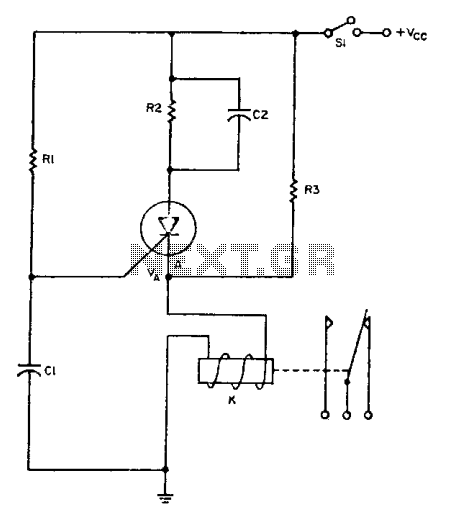
The relay operates for a specific duration, td, after power is applied, followed by an operating time, tc. The SCR activates when the voltage across capacitor Ci reaches a threshold voltage, VA. This action energizes the relay, which remains activated...

1976 dodge aspen wiring diagram
The Dodge Aspen was a compact car produced from 1976 to 1980 by Chrysler Corporation's Dodge division. The 1976 Aspen model year was available as a 2-door coupe, 4-door sedan, or 4-door station wagon, and it came in three trim...
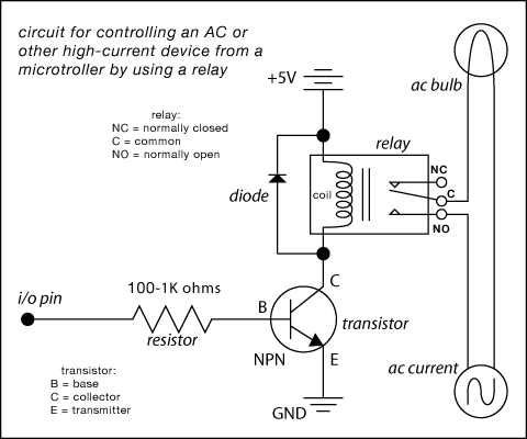
relay circuit diagram
Here are some circuit diagrams for driving relays from a microcontroller. Ensure the use of a 5-volt relay (this refers to the coil, not the load circuit) and verify that the relay has a sufficient rating for the load being...