


dome light dimmer
#555 timer
#dome light dimmer
#capacitor
#resistor
#retained accessory power
#car lighting
#voltage control
#custom automotive
#1969 Chevelle
#Dakota Digital
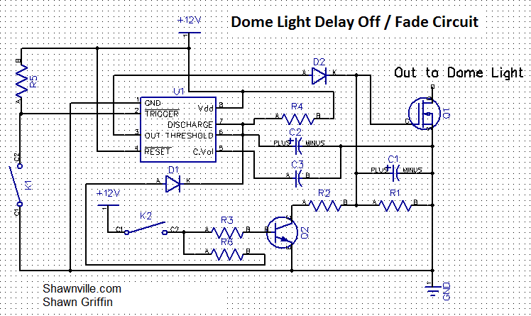
Description: A project is underway to create a custom electronic circuit for a 1969 Chevelle. The design aims to replicate a retained accessory power feature similar to a product offered by Dakota Digital, but at a lower cost. The circuit utilizes a 555 timer, where a capacitor (C2) and a resistor (R4) connected to pins 6 and 7 of the timer determine the duration for which the output on pin 3 remains high. Increasing the capacitance or resistance will extend the output duration.
The circuit design incorporates a standard 555 timer IC, which is widely used for timing applications. The configuration is set in monostable mode, where a trigger signal on pin 2 initiates the timing cycle. When the circuit is activated, the capacitor C2 begins to charge through the resistor R4. The time duration for which the output at pin 3 remains high can be calculated using the formula:
\[ T = 1.1 \times R4 \times C2 \]
where T is the time in seconds, R4 is the resistance in ohms, and C2 is the capacitance in farads. The choice of values for R4 and C2 will directly affect the performance of the circuit, allowing for customization based on the specific requirements of the retained accessory power feature.
Additionally, the circuit may include a diode for reverse polarity protection and a power supply input that can be connected to the vehicle's battery. Proper decoupling capacitors should be added near the power supply pins of the 555 timer to ensure stable operation. The output from pin 3 can be connected to a relay or transistor, allowing the control of higher current loads, such as the vehicle's accessory systems.
This design provides a cost-effective solution for integrating a retained accessory power feature into vintage vehicles, enhancing functionality while maintaining a classic aesthetic.I am building this for my 1969 Chevelle. Dakota Digital has something similar, but I didn`t want to spend $200 onit. Iam working on replicating the retained accessory powertoo. The capacitor (C2) & resistor (R4) connected to pins 6 & 7on the 555 timer controls how long the output on pin 3is high. Alarger capacitor or more resistance will give you moretime.
The circuit design incorporates a standard 555 timer IC, which is widely used for timing applications. The configuration is set in monostable mode, where a trigger signal on pin 2 initiates the timing cycle. When the circuit is activated, the capacitor C2 begins to charge through the resistor R4. The time duration for which the output at pin 3 remains high can be calculated using the formula:
\[ T = 1.1 \times R4 \times C2 \]
where T is the time in seconds, R4 is the resistance in ohms, and C2 is the capacitance in farads. The choice of values for R4 and C2 will directly affect the performance of the circuit, allowing for customization based on the specific requirements of the retained accessory power feature.
Additionally, the circuit may include a diode for reverse polarity protection and a power supply input that can be connected to the vehicle's battery. Proper decoupling capacitors should be added near the power supply pins of the 555 timer to ensure stable operation. The output from pin 3 can be connected to a relay or transistor, allowing the control of higher current loads, such as the vehicle's accessory systems.
This design provides a cost-effective solution for integrating a retained accessory power feature into vintage vehicles, enhancing functionality while maintaining a classic aesthetic.I am building this for my 1969 Chevelle. Dakota Digital has something similar, but I didn`t want to spend $200 onit. Iam working on replicating the retained accessory powertoo. The capacitor (C2) & resistor (R4) connected to pins 6 & 7on the 555 timer controls how long the output on pin 3is high. Alarger capacitor or more resistance will give you moretime.
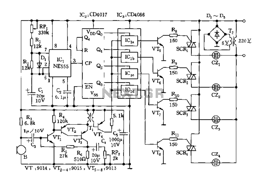
555 Music lantern controller circuit diagram
The circuit includes a controller that integrates an acoustic-electric conversion and amplification circuit, a clock pulse generator, a counting circuit, and a control circuit. It manages four accompanying music tracks and flashing lights. Microphones (MIC) convert sound into electrical signals,...
9 second digital readout countdown timer
This circuit provides a visual 9-second delay using a 7-segment digital readout LED. When the switch is closed, the CD4010 up/down counter is preset to 9, and the 555 timer is disabled with the output held high.
The circuit utilizes a...
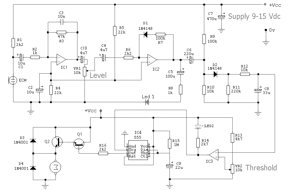
Alarm Circuit for Snoring Prevention by 555 Timer
The circuit was designed to create an alarm system that alerts a sleeping person to prevent snoring by utilizing a vibrator instead of an audio alert.
The circuit operates on the principle of detecting snoring sounds through a microphone or sound...
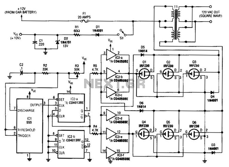
250W Inverter Circuit
A 555 timer (IC1) generates a 120-Hz signal that is fed to a CD4013BE flip-flop (IC1-a), which divides the input frequency by two to generate a 60-Hz clocking frequency for the FET array (Q1 through Q6). Transformer T1 is a...
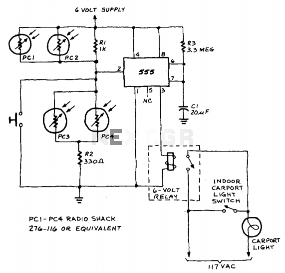
Auto light controller
A 555 timer integrated circuit (IC) functions in one-shot mode, triggered by light exposure to photoresistors. These photoresistors typically exhibit a resistance in the range of several megohms, which decreases to several hundred ohms under light conditions, allowing current from...
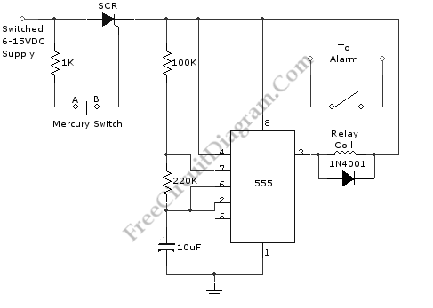
555-IC Timed Beeper/Alarm
This is a simple circuit of a beeper using a 555 timer. This circuit can be employed to energize lights, horns, or other signaling devices at any desired interval.
The 555 timer is a versatile integrated circuit widely used in various...
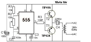
12V power inverter using 555 timer circuit
12V power inverter circuit utilizing a 555 timer for an electronic project.
The 12V power inverter circuit is designed to convert a DC voltage of 12 volts into an AC voltage suitable for powering small electronic devices. The core component of...
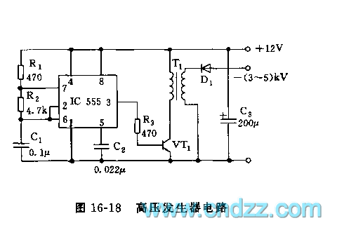
555 high voltage generator circuit
The high voltage generator depicted in figure 16-18 utilizes the 555 timer IC as its primary component. The oscillating voltage produced is enhanced through a step-up transformer. The astable multivibrator configuration comprises the 555 timer along with resistors R1 and...
Economy Timer 555 IC
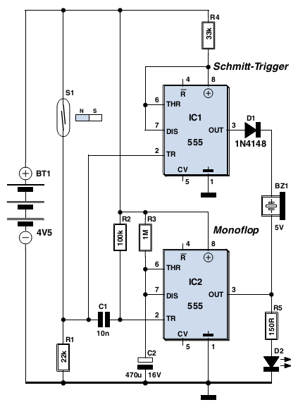
This circuit detects when a window is open (it can also be used with a door), indicates that the window is open by means of a red LED or a blinking LED, and emits a loud acoustic signal from an...