


Drag dedicated traffic control system
#traffic control
#electric driving
#material transport
#automation
#control system
#industrial equipment
#semi-manual operation
#plant modernization
Description: Electric driving is essential for modernizing plant material transport. Traditional control methods are primarily semi-manually operated automatic systems. To enhance efficiency, promote production automation, and reduce labor intensity, electrical automation for material transport is often implemented. This automation allows for driving operations to follow a predetermined sequence and fulfill various automatic control tasks. An example can be seen in an electroplating factory dedicated lane, where a PLC (Programmable Logic Controller) is utilized to create an automatic control system for the dedicated lane used in plating.
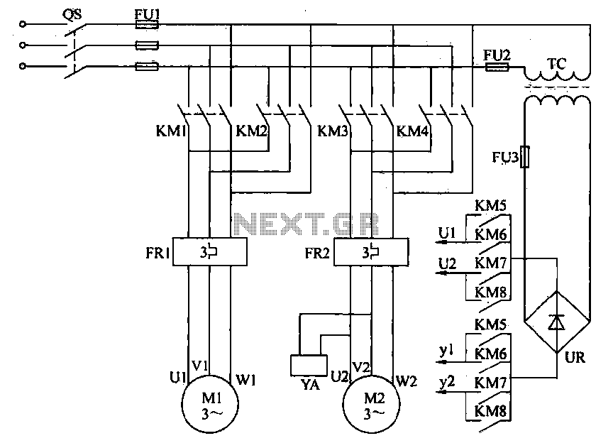
The drive system is designed for special vehicles that manage dragging and lifting motions using a three-phase AC induction motor. To lift heavy loads in the plating process, two J 02-12-4 motors are employed alongside mechanical reduction gearing. The control system for this drive is illustrated in Figure 26-35. Forward and backward motion, as well as up and down movements, are managed by reversing the motors. Dynamic braking is employed to ensure accurate stopping positions during these movements. Additionally, during the translation process, an electric motor with a lifting magnet brake is utilized to prevent the basket from falling due to its own weight.
In the schematic, contactors KM1 and KM2 control the forward and reverse operations of the motor, while KM3 and KM4 manage the up and down movements to facilitate lifting and lowering. Contactor KM6 controls the brakes for the vehicle's front and rear, and contactors KM7 and KM8 are responsible for the braking during lifting and lowering operations. Thermal relays FR1 and FR2 serve a protective function.
For PLC selection and address assignment, the Mitsubishi F1-40M type PLC is chosen based on the control requirements of the dedicated lane. This PLC features 24 input points and 16 output points. The number of I/O points in the plating control system varies with the number of plating tanks. For instance, with four plating tanks, there are 20 input points and 8 output points; each additional tank increases the input by two points—one for the slot limit switch and one for the slot selector switch—while the output points remain constant regardless of the number of plating baths. For systems requiring more plating baths, expansion units such as the F1-20E or F1-40E can be integrated. In this particular case with four plating baths, no expansion unit is necessary. The PLC address allocation table is configured accordingly to accommodate the system's needs.Electric driving is an important equipment for the modernization of the plant material transport, the traditional control methods, mostly semi-manually operated automatic contr ol mode. In many cases, in order to improve efficiency, promote production automation and reduce labor intensity, often to achieve electrical Ru moving traffic automation. To achieve automatic control, can make driving in accordance with a predetermined sequence and complete a series of requirements for automatic control work.
In this example, the electroplating factory dedicated lane, for example, the use of PLC constitute an automatic control system to realize the turtle plating dedicated lane from automatic control. (1) drive system design special vehicles before and after the fetters drag and lift motion by the three-phase AC induction motor.
To lift the heavy traffic of the plating amount, use two J 02-12-4 motor drag, and the use of mechanical reduction level. Drag the control system shown in Figure 26-35. Among them, driving forward and backward, up and down control by the motor reversing to implement now, when driving back and forth and down movement stopped using dynamic braking, to ensure accurate stop position.
In the translation process, the electric motor using the lifting magnet brake to prevent the basket fell by its own weight. Figure 26-35, the contact clamor KM1KM2 by controlling the front/rear of the motor is, reverse, forward and realize after driving back; contactor KM3/KM4 control up/down the motor to achieve increased traffic and fall; and KM6 control contactor KM5 row vehicle in front, rear brakes, contactors KM7 and KM8 driving control raising and lowering brake.
FR1 and FR2 for the thermal relay, from the security guard role. (2) PLC Selection and address assignment according to the control requirements of the dedicated lane, used Mitsubishi Fl-40M type PLC, the basic I/O points are: input 24 points and output 16 points. Driving in the plating PLC control system, PLCs I/O points with the number of plating tank varies. When the plating tank 4, a total of 20 points PLC input, output 8 points; each additional slot will increase the input of 2:00, one for controlling the slot limit switch, and one for slot selector switch ; regardless of the number of PLC output points with the plating bath.
If a larger number of plating bath, according to the need of expansion matched with the F series units, such as the use Fl-20E type or Fl-40E type Expansion Unit. In this case, the number of plating bath is 4, without increasing the expansion unit. PLCs u0 address allocation table
The drive system is designed for special vehicles that manage dragging and lifting motions using a three-phase AC induction motor. To lift heavy loads in the plating process, two J 02-12-4 motors are employed alongside mechanical reduction gearing. The control system for this drive is illustrated in Figure 26-35. Forward and backward motion, as well as up and down movements, are managed by reversing the motors. Dynamic braking is employed to ensure accurate stopping positions during these movements. Additionally, during the translation process, an electric motor with a lifting magnet brake is utilized to prevent the basket from falling due to its own weight.
In the schematic, contactors KM1 and KM2 control the forward and reverse operations of the motor, while KM3 and KM4 manage the up and down movements to facilitate lifting and lowering. Contactor KM6 controls the brakes for the vehicle's front and rear, and contactors KM7 and KM8 are responsible for the braking during lifting and lowering operations. Thermal relays FR1 and FR2 serve a protective function.
For PLC selection and address assignment, the Mitsubishi F1-40M type PLC is chosen based on the control requirements of the dedicated lane. This PLC features 24 input points and 16 output points. The number of I/O points in the plating control system varies with the number of plating tanks. For instance, with four plating tanks, there are 20 input points and 8 output points; each additional tank increases the input by two points—one for the slot limit switch and one for the slot selector switch—while the output points remain constant regardless of the number of plating baths. For systems requiring more plating baths, expansion units such as the F1-20E or F1-40E can be integrated. In this particular case with four plating baths, no expansion unit is necessary. The PLC address allocation table is configured accordingly to accommodate the system's needs.Electric driving is an important equipment for the modernization of the plant material transport, the traditional control methods, mostly semi-manually operated automatic contr ol mode. In many cases, in order to improve efficiency, promote production automation and reduce labor intensity, often to achieve electrical Ru moving traffic automation. To achieve automatic control, can make driving in accordance with a predetermined sequence and complete a series of requirements for automatic control work.
In this example, the electroplating factory dedicated lane, for example, the use of PLC constitute an automatic control system to realize the turtle plating dedicated lane from automatic control. (1) drive system design special vehicles before and after the fetters drag and lift motion by the three-phase AC induction motor.
To lift the heavy traffic of the plating amount, use two J 02-12-4 motor drag, and the use of mechanical reduction level. Drag the control system shown in Figure 26-35. Among them, driving forward and backward, up and down control by the motor reversing to implement now, when driving back and forth and down movement stopped using dynamic braking, to ensure accurate stop position.
In the translation process, the electric motor using the lifting magnet brake to prevent the basket fell by its own weight. Figure 26-35, the contact clamor KM1KM2 by controlling the front/rear of the motor is, reverse, forward and realize after driving back; contactor KM3/KM4 control up/down the motor to achieve increased traffic and fall; and KM6 control contactor KM5 row vehicle in front, rear brakes, contactors KM7 and KM8 driving control raising and lowering brake.
FR1 and FR2 for the thermal relay, from the security guard role. (2) PLC Selection and address assignment according to the control requirements of the dedicated lane, used Mitsubishi Fl-40M type PLC, the basic I/O points are: input 24 points and output 16 points. Driving in the plating PLC control system, PLCs I/O points with the number of plating tank varies. When the plating tank 4, a total of 20 points PLC input, output 8 points; each additional slot will increase the input of 2:00, one for controlling the slot limit switch, and one for slot selector switch ; regardless of the number of PLC output points with the plating bath.
If a larger number of plating bath, according to the need of expansion matched with the F series units, such as the use Fl-20E type or Fl-40E type Expansion Unit. In this case, the number of plating bath is 4, without increasing the expansion unit. PLCs u0 address allocation table

Objects in Flux
The Open Source Automation project is a free automation software that operates on Windows and does not require programming for setup. It features a user-friendly graphical interface and includes unique functionalities that are not typically found in high-end security and...
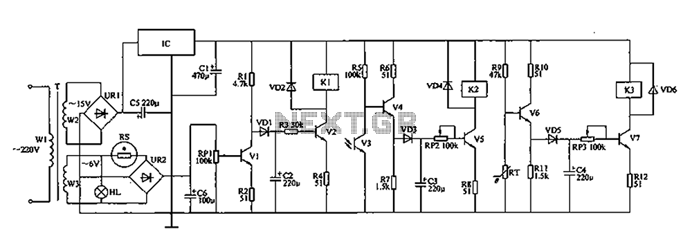
Coop automatic controller circuit diagram
The automatic controller for a chicken coop is designed to automatically regulate light, temperature, and humidity, thereby enhancing egg production and survival rates of chickens. This device is intended for specialized poultry households in rural areas. The circuit operates through...
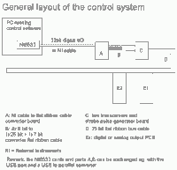
Cold Atom Control System for PC
We have developed a powerful yet inexpensive and easy to construct experiment control system. The construction of the system together with the control software is described here. All circuits and software are free to download and use for nonprofit. The...
Process-Control
The Measured Value and the Setpoint are two inputs to a control system. The Measured Value is the amplified input from a transducer or sensor that monitors a parameter requiring control, such as pressure or temperature. The Setpoint is the...
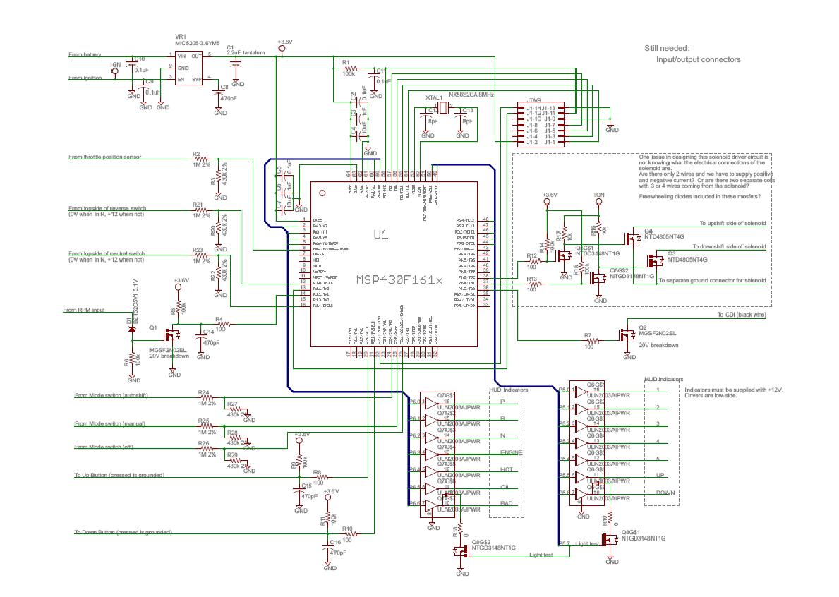
Electrical_Subsystem
The following data and mapping pertain to the 2-D shift mapping algorithm that the controller will utilize to determine when and if a shift should occur. The solid lines on the graph indicate up-shift boundaries, while the dashed lines represent...
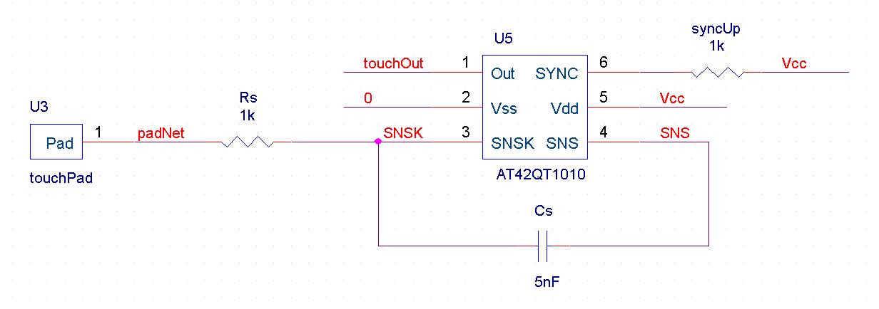
automatic pet feeder
An automatic feeder dispenses food based on the activation of a series of buttons, which interface with a system controller and a food dispenser. The system is designed for intelligent processing of inputs and outputs, allowing dynamic configuration of button...
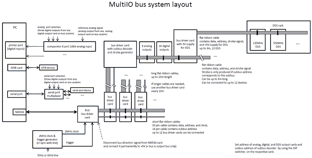
Control System for Cold Atom Experiments
We have developed a powerful yet inexpensive and easy to construct experiment control system. The construction of the system together with the control software is described here. All circuits and software are free to download and use for nonprofit. The...