


Electronic-car-horn
#LM556
#dual oscillator
#two-tone oscillator
#amplifier
#audio
#frequency control
#potentiometer
#automotive
#car horn
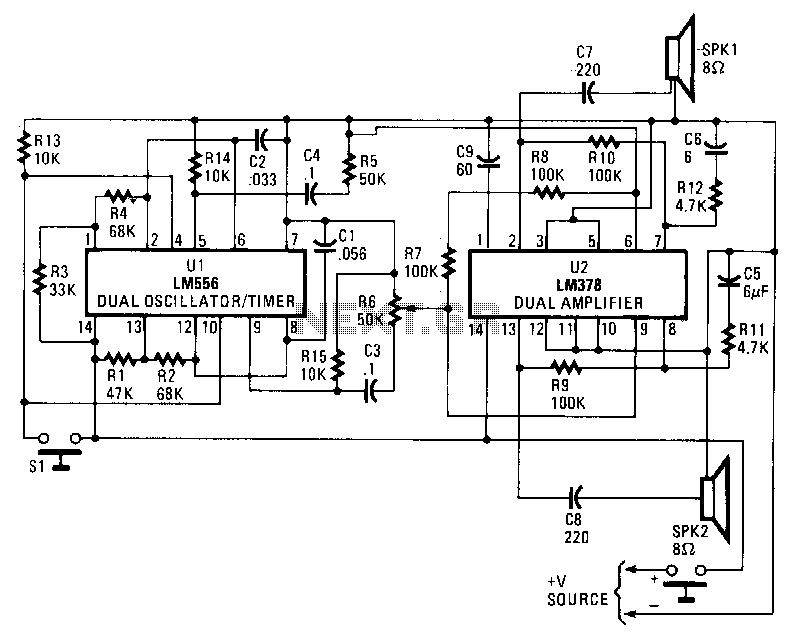
Description: An LM556 dual oscillator/timer, U1, is configured as a two-tone oscillator that drives U2, a dual 4-watt amplifier. One of the oscillators, connected to pins 1 to 6 of U1, generates an upper frequency signal of approximately 200 Hz, while the second oscillator, connected to pins 8 to 13, produces a lower frequency signal of about 140 Hz. The frequencies can be adjusted by changing the values of capacitors C2 and C3. The outputs of U1, located at pins 9 and 5, are connected to separate potentiometers to allow for control over volume and balance. Each half of U2 generates 4 watts of audio, which is delivered to two 8-ohm loudspeakers through capacitors C7 and C8.
The circuit employs the LM556 integrated circuit, which is a versatile dual timer capable of generating precise timing and oscillation signals. In this configuration, it operates as a two-tone generator, producing distinct audio frequencies that can be used in various applications, such as sound effects or alarms. The upper frequency oscillator, operating at approximately 200 Hz, can be utilized to create a higher-pitched tone, while the lower frequency oscillator at about 140 Hz produces a deeper sound.
Adjustments to the audio frequencies are facilitated by capacitors C2 and C3, which influence the timing characteristics of the oscillators. By altering their capacitance values, the user can fine-tune the output frequencies to achieve the desired sound profile.
The output signals from the LM556 are routed to potentiometers connected to pins 9 and 5, allowing for user control over volume and balance. This feature enhances the circuit's usability in real-world applications, enabling adjustments to suit different environments or listener preferences.
The dual 4-watt amplifier, represented by U2, is designed to amplify the audio signals generated by the LM556. Each half of the amplifier is responsible for delivering 4 watts of power, resulting in a total output sufficient to drive two 8-ohm loudspeakers. Capacitors C7 and C8 serve as coupling capacitors, ensuring that the amplified audio signals are transmitted effectively to the speakers while blocking any DC components that could damage the speakers.
Overall, this circuit design provides a straightforward yet effective means of generating and amplifying two distinct audio tones, suitable for a variety of electronic sound applications.An LM556 dual oscillator/timer, U1, configured as a two-tone oscillator drives U2, a dual4-watt amplifier. One of the oscillators, pins 1 to 6, contained in U1 produces the upper frequency signal of about 200 Hz, while the second oscillator, pins 8 to 13, provides the lower frequency signal of about 140Hz.
Increase or decrease the frequencies by changing the values of C2 and C3. U1"s outputs, pins 9 and 5, are connected to separate potentiometers to provide control over volume and balance. Each half of U2 produces 4 W of audio that is delivered to two 8-0 loudspeakers via capacitors C7 and C8.
The circuit employs the LM556 integrated circuit, which is a versatile dual timer capable of generating precise timing and oscillation signals. In this configuration, it operates as a two-tone generator, producing distinct audio frequencies that can be used in various applications, such as sound effects or alarms. The upper frequency oscillator, operating at approximately 200 Hz, can be utilized to create a higher-pitched tone, while the lower frequency oscillator at about 140 Hz produces a deeper sound.
Adjustments to the audio frequencies are facilitated by capacitors C2 and C3, which influence the timing characteristics of the oscillators. By altering their capacitance values, the user can fine-tune the output frequencies to achieve the desired sound profile.
The output signals from the LM556 are routed to potentiometers connected to pins 9 and 5, allowing for user control over volume and balance. This feature enhances the circuit's usability in real-world applications, enabling adjustments to suit different environments or listener preferences.
The dual 4-watt amplifier, represented by U2, is designed to amplify the audio signals generated by the LM556. Each half of the amplifier is responsible for delivering 4 watts of power, resulting in a total output sufficient to drive two 8-ohm loudspeakers. Capacitors C7 and C8 serve as coupling capacitors, ensuring that the amplified audio signals are transmitted effectively to the speakers while blocking any DC components that could damage the speakers.
Overall, this circuit design provides a straightforward yet effective means of generating and amplifying two distinct audio tones, suitable for a variety of electronic sound applications.An LM556 dual oscillator/timer, U1, configured as a two-tone oscillator drives U2, a dual4-watt amplifier. One of the oscillators, pins 1 to 6, contained in U1 produces the upper frequency signal of about 200 Hz, while the second oscillator, pins 8 to 13, provides the lower frequency signal of about 140Hz.
Increase or decrease the frequencies by changing the values of C2 and C3. U1"s outputs, pins 9 and 5, are connected to separate potentiometers to provide control over volume and balance. Each half of U2 produces 4 W of audio that is delivered to two 8-0 loudspeakers via capacitors C7 and C8.

Audio Fader
In this circuit, Q1 serves as a simple amplifier with gain control provided by a variable emitter resistance supplied by FET Q2. When switch SI is in the up position, capacitor C3 discharges through resistor R5, resulting in a decrease...
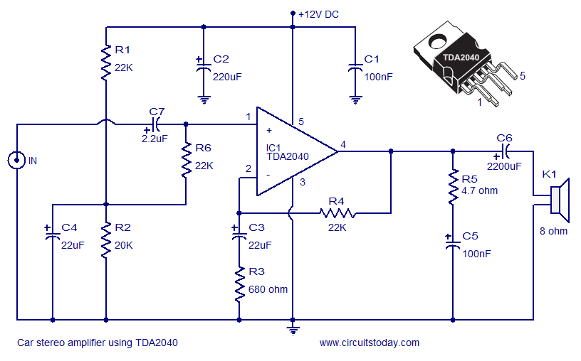
Car Amplifier Circuit Schematic using TDA2040 Integrated Audio Amplifier
A car stereo amplifier circuit utilizing the TDA2040 is presented here. The TDA2040 is a monolithic integrated audio amplifier that functions in Class AB mode. This integrated circuit features built-in short circuit protection and thermal shutdown capabilities, and it can...
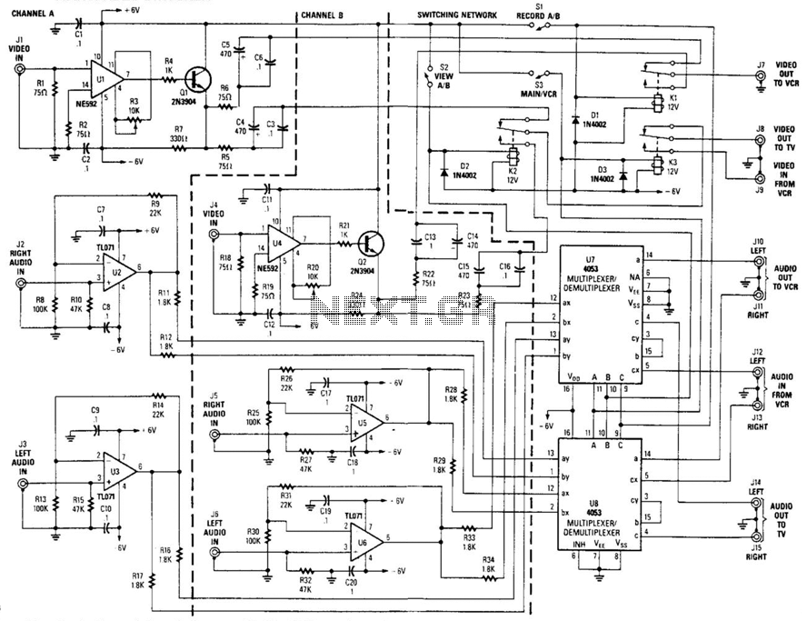
Audio/Video Switcher
This circuit is a two-channel baseband video switcher. Buffer amplifiers U1/Q1, U4/Q4, and associated components produce a buffered 75-ohm video signal, which is routed to the switching network K1/K2/K3. Relay K1 selects either of the two video amplifiers and feeds...

Voltage Regulator For Cars And Motorcycles
This regulator circuit can be used on an alternator that has one field terminal grounded. When the input voltage becomes too high, Q1 conducts, and the base of Q2 is driven toward ground, reducing the voltage fed to Q3. This...
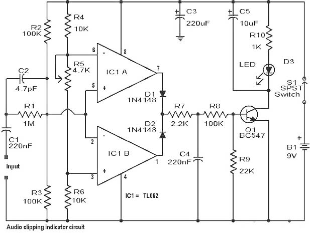
Audio Clipping Detector Circuit
Clipping is a significant issue that leads to distortion in amplifiers. It results in the amplitude level of a waveform dropping abruptly before it reaches its intended limit. This document presents a straightforward circuit designed to detect clipping in a...
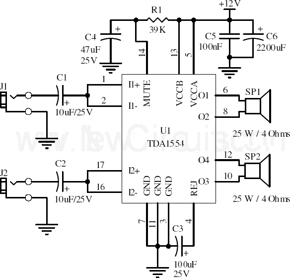
Circuit 22W Stereo Amplifier Using TDA1554
This document presents a 22-watt stereo audio power amplifier circuit diagram utilizing the TDA1554 integrated circuit from NXP Semiconductors (formerly known as PHILIPS Semiconductors). The circuit is designed to amplify stereo signals effectively. It dissipates approximately 28 watts of heat,...
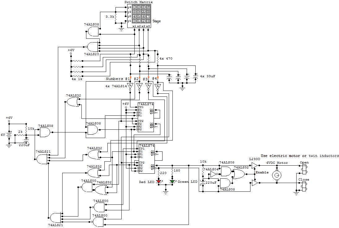
Audio Electronic Locker Circuit Schematic Picture
All the adapted numbers of the cipher are in the aforementioned line. To set the adjustment of the cardinal of the code, we accept to set the acceptable affiliation amid the bulge of the 7414 ascribe and the adapted bulge...

Simple Hybrid Audio Amplifier
The debate continues regarding whether valves or transistors are superior. This discussion will not be addressed here. However, if one cannot make their…
The comparison between valves (vacuum tubes) and transistors has been a longstanding topic in the field of electronics,...
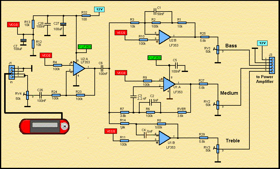
Audio MP3 Car Amplifier Schematic Circuits 150W
These accessories are low-cost, high-speed, bifet-input operational amplifiers utilizing internally compensated voltage (BI-FET II technology). They require low supply voltages while offering a wide gain bandwidth product and fast slew rate. Additionally, well-matched high voltage JFET input devices accommodate very...