


Engine Block Heater Minder Circuit
#engine block heater
#power indicator
#NE1
#PL1
#SI
#automotive
#heater monitoring
#vehicle
#cold weather
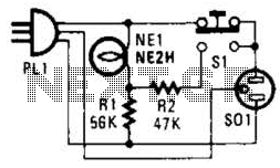
Description: If residing in a cold climate, it is reassuring to confirm the functionality of an engine-block heater. This device indicates whether the heater is operational. To use, connect PL1 to a power outlet; the NE1 indicator should illuminate. Next, plug in the block heater. Pressing SI should result in a brighter indicator. If the indicator does not brighten, the block heater may be faulty or non-functional.
The engine-block heater status indicator circuit is designed to provide a visual confirmation of the heater's operational status, which is critical in extremely low temperatures. The primary components of this circuit include a power input connector (PL1), an indicator light (NE1), a block heater connection, and a switch (SI) for user interaction.
PL1 serves as the connection point for the circuit to the AC power supply, ensuring that the necessary voltage is available for operation. Upon connecting PL1 to the power outlet, NE1, an LED indicator, is powered on, signaling that the circuit is receiving power. This initial step is crucial for confirming that the system is operational before proceeding to the next step.
The block heater is then connected to the circuit, providing the necessary heating element for the engine. The switch (SI) is integrated into the circuit to allow the user to manually check the heater's functionality. When SI is depressed, it completes a secondary circuit that increases the current flow through NE1, resulting in a brighter illumination of the indicator light. This increase in brightness serves as an immediate visual cue that the block heater is functioning correctly.
If the NE1 indicator does not brighten upon pressing SI, it signifies a potential fault in the block heater, indicating that it may be open or inoperative. This functionality is essential for users in cold climates, as it helps prevent engine damage due to inadequate heating during low temperatures. The circuit design ensures that users can easily assess the operational status of their engine-block heater, providing peace of mind during harsh winter conditions. If you live in the frozen north, knowing your engine-block heater is working is a comfort. This device will let you know if yours is okay. Plug in PL1 to your power outlet. NE1 should light. Then, plug in the block heater. Depressing SI should cause the indicator to get brighter. If not, your block heater might be open and inoperative.
The engine-block heater status indicator circuit is designed to provide a visual confirmation of the heater's operational status, which is critical in extremely low temperatures. The primary components of this circuit include a power input connector (PL1), an indicator light (NE1), a block heater connection, and a switch (SI) for user interaction.
PL1 serves as the connection point for the circuit to the AC power supply, ensuring that the necessary voltage is available for operation. Upon connecting PL1 to the power outlet, NE1, an LED indicator, is powered on, signaling that the circuit is receiving power. This initial step is crucial for confirming that the system is operational before proceeding to the next step.
The block heater is then connected to the circuit, providing the necessary heating element for the engine. The switch (SI) is integrated into the circuit to allow the user to manually check the heater's functionality. When SI is depressed, it completes a secondary circuit that increases the current flow through NE1, resulting in a brighter illumination of the indicator light. This increase in brightness serves as an immediate visual cue that the block heater is functioning correctly.
If the NE1 indicator does not brighten upon pressing SI, it signifies a potential fault in the block heater, indicating that it may be open or inoperative. This functionality is essential for users in cold climates, as it helps prevent engine damage due to inadequate heating during low temperatures. The circuit design ensures that users can easily assess the operational status of their engine-block heater, providing peace of mind during harsh winter conditions. If you live in the frozen north, knowing your engine-block heater is working is a comfort. This device will let you know if yours is okay. Plug in PL1 to your power outlet. NE1 should light. Then, plug in the block heater. Depressing SI should cause the indicator to get brighter. If not, your block heater might be open and inoperative.
Automotive burglar alarm
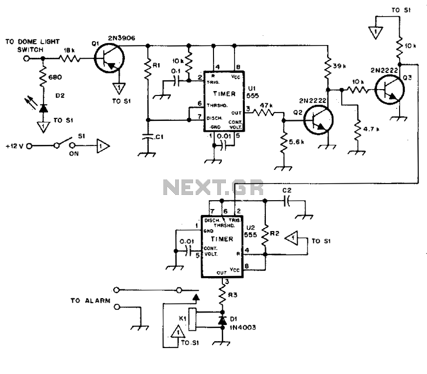
The alarm activates after a 13-second delay and remains active for 1 to 1.5 minutes before automatically resetting. It can also be deactivated and reset by opening and reclosing switch SI.
The described circuit functions as a delay-triggered alarm system, incorporating...
Three-Level Audio Power Indicator
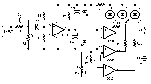
This circuit is designed to indicate the power output level of any audio amplifier. It is simple, portable, and displays three power levels that can be set to any desired value. For a standard HiFi stereo power amplifier, such as...
Automotive charger for ni-cad battery packs
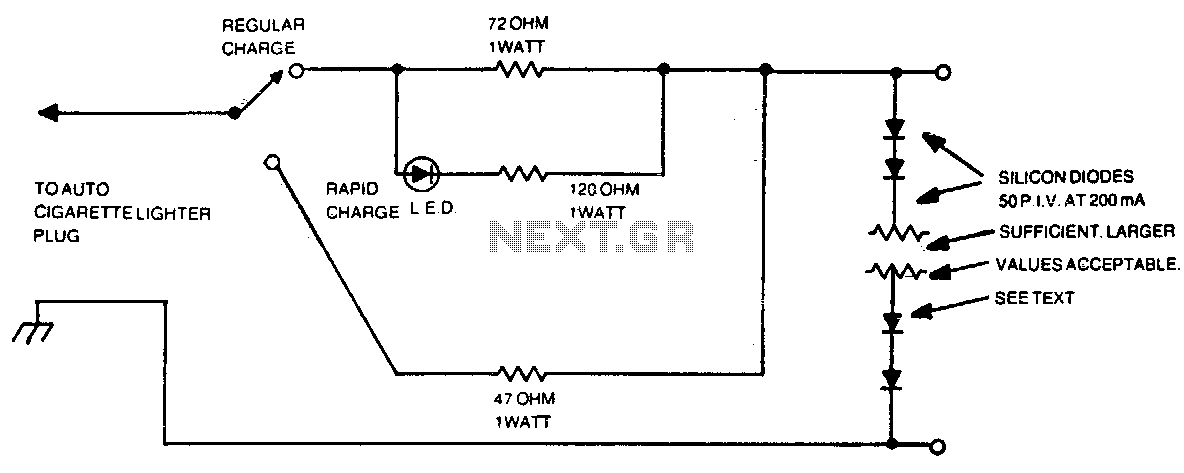
The number of silicon diodes across the output is determined by the voltage of the battery pack. Each diode is considered at 0 volts. For example, a 10-volt pack would require 10/0 = 157, or 16 diodes.
In the context of...

Voltage Regulator For Cars And Motorcycles
This regulator circuit can be used on an alternator that has one field terminal grounded. When the input voltage becomes too high, Q1 conducts, and the base of Q2 is driven toward ground, reducing the voltage fed to Q3. This...
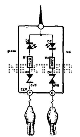
Automotive Electrical Tester
This compact tester is designed for checking vehicle electrical circuits. Two LEDs indicate whether one of the clips is connected to the positive supply line (red) or to ground (green). The unit is powered by the vehicle battery. It is...
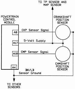
Camshaft Position Sensor
AutoZone Repair Guide for Engine Performance and Emission Control Components and Systems, specifically focusing on the Camshaft Position Sensor.
The Camshaft Position Sensor (CMP) is a critical component in modern internal combustion engines, playing a vital role in the management of...
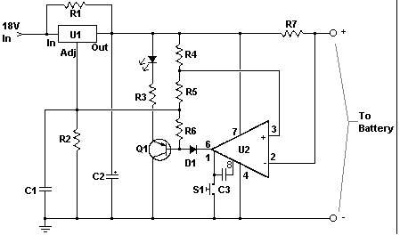
Car battery charger Automative car and motorcycle schematics
The circuit is designed to operate with an external power supply, which is why it does not include a transformer, rectifier, or filter capacitors in the schematic. However, these components can be added if desired. To utilize the circuit, connect...
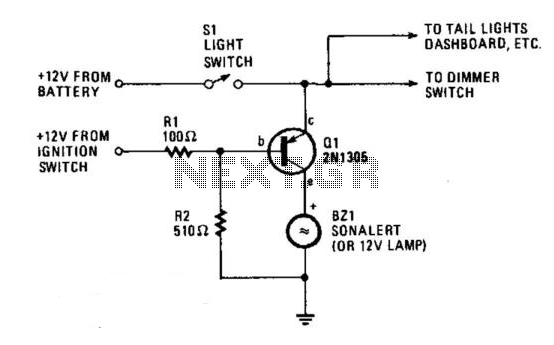
Automobile Lights-On Reminder
The circuit provides a visible or audible warning when the headlights are on. It utilizes a 2N1305 transistor as a switch to activate either a Sonalert tone generator or a small 12-V lamp. The operating current for the transistor is...
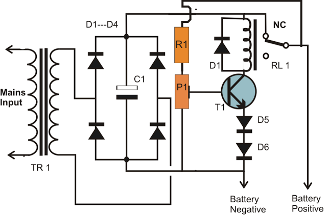
simplest smf automotive battery charger
A simple battery charger circuit is described, utilizing a single transistor for voltage detection and automatically disconnecting the battery from the supply when fully charged. The circuit's high voltage trip point is set to switch off the charging voltage when...