


fcd fuel cut defencer
#FCD
#fuel cut
#automotive
#engine control
#modification
#circuit design
#TII
#vehicle electronics
#performance tuning
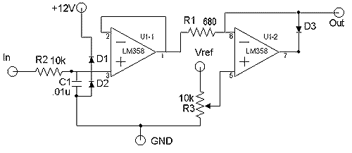
Description: This article introduces a straightforward Fuel Cut Defender (FCD) circuit that can be assembled by individuals with moderate electronics skills. It discusses the necessity of an FCD, its advantages over other designs, and the underlying operational theory. By the conclusion of this article, readers will gain a better understanding of how their TII functions and some basic electronics principles. An FCD is designed to prevent the stock Engine Control Unit (ECU) from cutting off fuel to the rear rotor when the boost surpasses a predetermined level. This maximum safe boost level is encoded in the firmware of the engine management unit and cannot be altered without reprogramming the ECU, typically set at approximately 8.6 psi. The FCD operates by misleading the ECU regarding the actual boost pressure. It is installed between the boost sensor and the ECU, modifying the boost pressure signal so that when boost pressure exceeds the safe limit, the ECU continues to receive a signal that remains within acceptable levels. This manipulation has immediate consequences; as boost increases, the ECU must provide more fuel to the engine for optimal operation. However, as the FCD alters the signal, the ECU may under-compensate for the increased pressure, leading to a lean air-fuel mixture. Initially, minor errors may only impact efficiency, but larger discrepancies can result in detonation, particularly under high boost pressures and elevated intake temperatures, which can severely damage the engine. Therefore, it is crucial to use an FCD alongside fuel enrichment and efficient intercooling to prevent engine damage. The ideal FCD should maintain the boost signal until it nears the cutoff level, at which point it should hold the signal below the critical threshold. This function can be achieved using a circuit element known as a clamp. The FCD circuit presented utilizes an active clamp that effectively performs this task. The output of FCD #1 follows the input until it reaches a clamp voltage of 3.33 V (approximately 6 psi), at which point the output stabilizes. Conversely, FCD #2 reduces the input by a percentage, creating an error across the entire range, which is not desirable. The presented FCD operates similarly to FCD #1 but has a clamping voltage raised to 3.65 V (about 7.9 psi). Notably, the output is 0.05 V lower than the input until the clamping voltage is reached. This issue has been resolved by changing the resistor R1 from 2.2k ohms to 680 ohms, resulting in an output that is now within 0.02 V of the input up to the clamping voltage. The measurements were taken with the FCD connected to the TII boost sensor and wiring harness to closely simulate actual operating conditions, with pressure readings obtained from a diagnostic pressure/vacuum gauge.
The FCD circuit design incorporates essential components such as resistors, capacitors, and an operational amplifier to achieve the desired clamping behavior. The active clamp configuration allows for dynamic adjustment of the output signal based on the input boost pressure. The operational amplifier is configured in a non-inverting mode to ensure that the output closely tracks the input until the clamping threshold is reached.
The circuit may include a voltage reference source to set the clamping voltage accurately. This voltage reference can be derived from a Zener diode or a precision voltage reference IC that ensures stable operation across varying temperatures and supply voltages.
The feedback loop within the operational amplifier configuration is crucial for maintaining the desired output characteristics. The choice of resistor values in the feedback path directly influences the response time and accuracy of the clamping action.
Furthermore, the layout of the circuit should minimize noise and interference, particularly in automotive environments where electromagnetic interference is prevalent. Shielding and careful routing of signal traces can enhance the reliability of the FCD circuit.
In conclusion, the FCD circuit serves as a critical component for managing boost pressure in performance applications, providing a safeguard against fuel cut-off while maintaining engine performance. Proper implementation and understanding of the circuit's operation are essential for ensuring safe and efficient engine operation under increased boost conditions.This article presents a simple FCD circuit that can be built by anyone with moderate electronics assembly expertise. In addition, the article covers the reasons why an FCD is needed, why this FCD is superior to other FCD designs, and the theory of operation.
By the time you are done reading this article, you will hopefully understand a little more about how your TII works, and a little electronics as well. The FCD (acronym for Fuel Cut Defencer) is any device that prevents the stock ECU from cutting fuel to the rear rotor when the boost exceeds a preset boost level. This maximum safe boost level and behavior is coded into the firm ware in the engine management unit and can not be changed without reprogramming the ECU.
The maximum allowed boost pressure is about 8. 6 psi. The way an FCD defeats the fuel cut is by lying to the ECU about what the boost pressure is. The FCD is placed betw1een the boost sensor and the ECU where it modifies the boost pressure signal by some amount so that as the boost pressure rises above the preset "safe limit", the ECU continues to see a signal that is below the limit. There are a couple of immediate consequences to this fooling around. As the boost rises, the ECU must increase the amount of fuel being delivered to the engine in order to maintain safe and efficient operation.
As the FCD starts lying to the ECU, the ECU will begin to under-compensate for the rise in pressure leading to a gradual leaning of the air-fuel mixture. The amount of error increases as the boost rises. For relatively small errors, the only penalty is efficiency. As the error gets larger, however, detonation becomes likely, exacerbated by the high boost pressures and accompanying high intake charge temperatures.
Detonation under these conditions will quickly kill an engine. So, before we go any further, be forewarned that using an FCD and increasing boost pressure without also compensating for the ECU error with fuel enrichment (and preferably more efficient intercooling) can cause serious damage to your engine! What you would like to have is an FCD that leaves the boost signal alone until it approaches the cutoff level, and then kicks in, holding the signal below the critical level.
This can be accomplished with a circuit element called a clamp. The FCD circuit described in this article utilizes an active clamp which performs the necessary function very efficiently. As you can see from the graph, FCD #1 is a clamp circuit. The output follows the input until the clamp voltage of 3. 33 V (about 6 psi) is reached. At this point the output stops rising. FCD #2 works by reducing the input by a percentage. This creates an error across the entire range, as opposed to only when the boost is over the limit. (At a safe 5. 5 psi, the computer is only seeing 4 psi. ) This is not the desired behavior. Our FCD works similarly to FCD #1, except we have raised the clamping voltage to 3. 65V (about 7. 9 psi). NOTE: If you look closely at the graph, you can see that our FCD has an output that is 0. 05 V below the input up to the clamping voltage. I have since fixed this problem by changing R1 from 2. 2k ohms to 680 ohms. The FCD output is now within 0. 02V of the input, right up to the clamping voltage. Sorry, I didn`t have time to rerun the numbers. The measurements above were obtained with the FCD under test connected to the TII boost sensor and TII wiring harness in order to simulate actual operating conditions as closely as possible.
Pressures were read on a diagnostic pressure/vacuum gauge. If you are interested in it, I would be happy to send you the Excel spreadsheet containing
The FCD circuit design incorporates essential components such as resistors, capacitors, and an operational amplifier to achieve the desired clamping behavior. The active clamp configuration allows for dynamic adjustment of the output signal based on the input boost pressure. The operational amplifier is configured in a non-inverting mode to ensure that the output closely tracks the input until the clamping threshold is reached.
The circuit may include a voltage reference source to set the clamping voltage accurately. This voltage reference can be derived from a Zener diode or a precision voltage reference IC that ensures stable operation across varying temperatures and supply voltages.
The feedback loop within the operational amplifier configuration is crucial for maintaining the desired output characteristics. The choice of resistor values in the feedback path directly influences the response time and accuracy of the clamping action.
Furthermore, the layout of the circuit should minimize noise and interference, particularly in automotive environments where electromagnetic interference is prevalent. Shielding and careful routing of signal traces can enhance the reliability of the FCD circuit.
In conclusion, the FCD circuit serves as a critical component for managing boost pressure in performance applications, providing a safeguard against fuel cut-off while maintaining engine performance. Proper implementation and understanding of the circuit's operation are essential for ensuring safe and efficient engine operation under increased boost conditions.This article presents a simple FCD circuit that can be built by anyone with moderate electronics assembly expertise. In addition, the article covers the reasons why an FCD is needed, why this FCD is superior to other FCD designs, and the theory of operation.
By the time you are done reading this article, you will hopefully understand a little more about how your TII works, and a little electronics as well. The FCD (acronym for Fuel Cut Defencer) is any device that prevents the stock ECU from cutting fuel to the rear rotor when the boost exceeds a preset boost level. This maximum safe boost level and behavior is coded into the firm ware in the engine management unit and can not be changed without reprogramming the ECU.
The maximum allowed boost pressure is about 8. 6 psi. The way an FCD defeats the fuel cut is by lying to the ECU about what the boost pressure is. The FCD is placed betw1een the boost sensor and the ECU where it modifies the boost pressure signal by some amount so that as the boost pressure rises above the preset "safe limit", the ECU continues to see a signal that is below the limit. There are a couple of immediate consequences to this fooling around. As the boost rises, the ECU must increase the amount of fuel being delivered to the engine in order to maintain safe and efficient operation.
As the FCD starts lying to the ECU, the ECU will begin to under-compensate for the rise in pressure leading to a gradual leaning of the air-fuel mixture. The amount of error increases as the boost rises. For relatively small errors, the only penalty is efficiency. As the error gets larger, however, detonation becomes likely, exacerbated by the high boost pressures and accompanying high intake charge temperatures.
Detonation under these conditions will quickly kill an engine. So, before we go any further, be forewarned that using an FCD and increasing boost pressure without also compensating for the ECU error with fuel enrichment (and preferably more efficient intercooling) can cause serious damage to your engine! What you would like to have is an FCD that leaves the boost signal alone until it approaches the cutoff level, and then kicks in, holding the signal below the critical level.
This can be accomplished with a circuit element called a clamp. The FCD circuit described in this article utilizes an active clamp which performs the necessary function very efficiently. As you can see from the graph, FCD #1 is a clamp circuit. The output follows the input until the clamp voltage of 3. 33 V (about 6 psi) is reached. At this point the output stops rising. FCD #2 works by reducing the input by a percentage. This creates an error across the entire range, as opposed to only when the boost is over the limit. (At a safe 5. 5 psi, the computer is only seeing 4 psi. ) This is not the desired behavior. Our FCD works similarly to FCD #1, except we have raised the clamping voltage to 3. 65V (about 7. 9 psi). NOTE: If you look closely at the graph, you can see that our FCD has an output that is 0. 05 V below the input up to the clamping voltage. I have since fixed this problem by changing R1 from 2. 2k ohms to 680 ohms. The FCD output is now within 0. 02V of the input, right up to the clamping voltage. Sorry, I didn`t have time to rerun the numbers. The measurements above were obtained with the FCD under test connected to the TII boost sensor and TII wiring harness in order to simulate actual operating conditions as closely as possible.
Pressures were read on a diagnostic pressure/vacuum gauge. If you are interested in it, I would be happy to send you the Excel spreadsheet containing
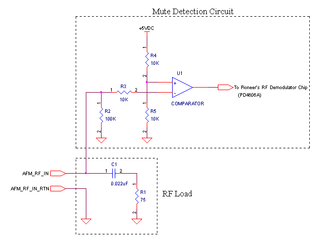
Pioneer CLD-1950
This modification is to be performed at your own risk, and there is no guarantee that it will work for you. Improper installation of this design may result in damage to you and/or your laserdisc player. This website does not...
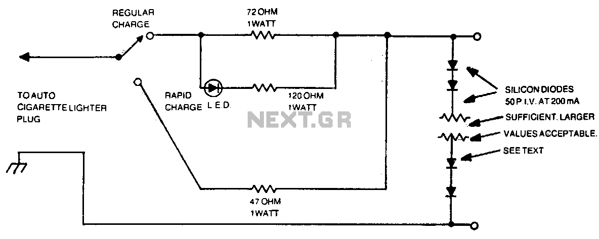
Automotive charger for ni-cad battery packs
The number of silicon diodes across the output is determined by the voltage of the battery pack. Each diode is considered at 0 volts. For example, a 10-volt pack would require 10/0 = 157, or 16 diodes.
In the context of...

Voltage Regulator For Cars And Motorcycles
This regulator circuit can be used on an alternator that has one field terminal grounded. When the input voltage becomes too high, Q1 conducts, and the base of Q2 is driven toward ground, reducing the voltage fed to Q3. This...
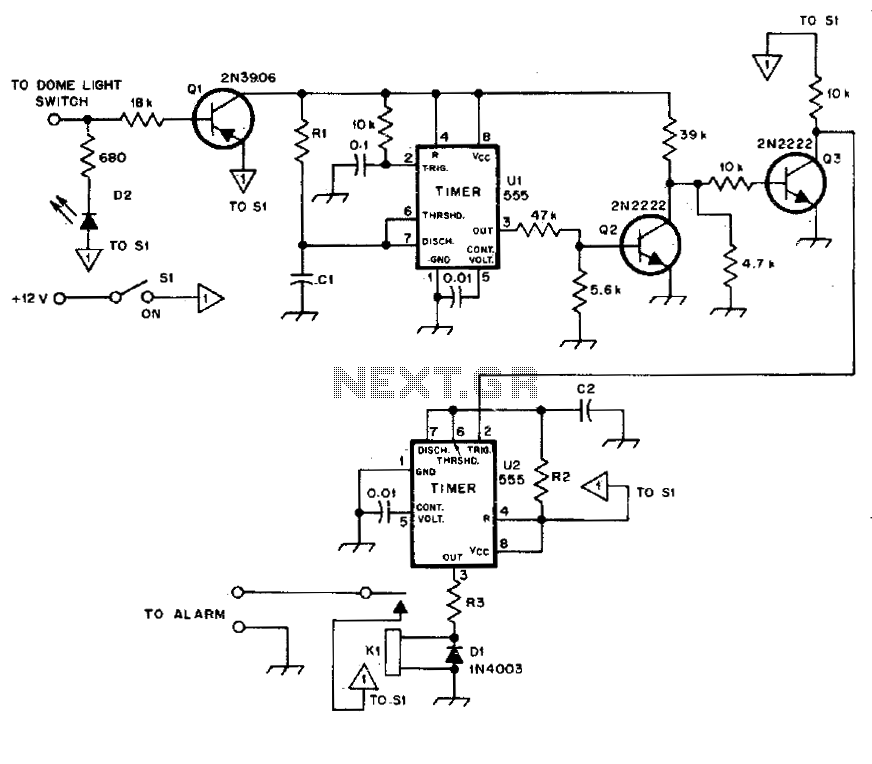
Automotive burglar alarm
The alarm activates after a 13-second delay and remains active for 1 to 1.5 minutes before automatically resetting. It can also be deactivated and reset by opening and reclosing switch SI.
The described circuit functions as a delay-triggered alarm system, incorporating...
Electronic Projects
This program includes circuit design CAD, simulation, and auto-routing PC layout. PSPICE is also utilized at Unisys, which offers more capabilities but costs six times as much and requires annual renewal. With these requirements and others in mind, a variation...
Automobile Lights-On Reminder
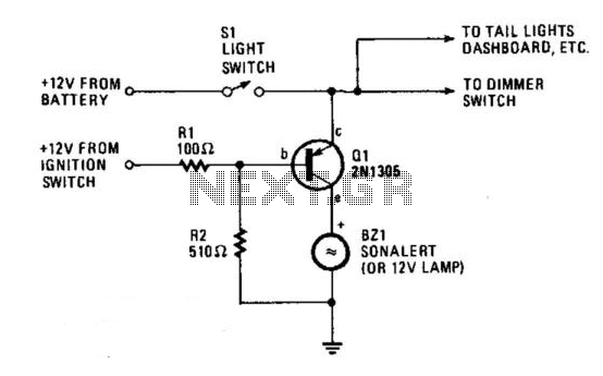
The circuit provides a visible or audible warning when the headlights are on. It utilizes a 2N1305 transistor as a switch to activate either a Sonalert tone generator or a small 12-V lamp. The operating current for the transistor is...
Automotive Electrical Tester
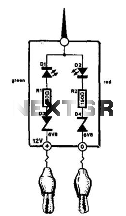
This compact tester is designed for checking vehicle electrical circuits. Two LEDs indicate whether one of the clips is connected to the positive supply line (red) or to ground (green). The unit is powered by the vehicle battery. It is...
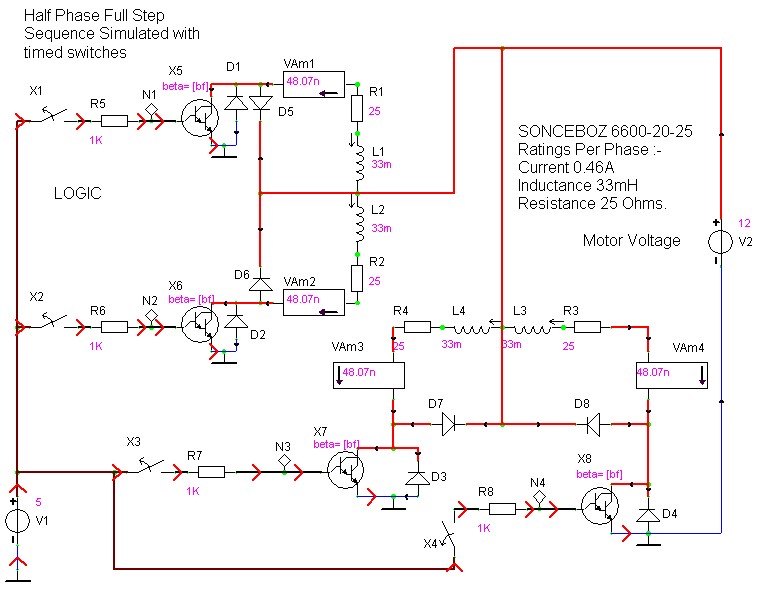
case stepper
Beige Bag Software has been offering affordable and innovative circuit design tools since 1990. B2 Spice provides schematics as well as analog, digital, and mixed-mode electronic circuit simulation. It integrates with EAGLE and CADSTAR PCB software.
B2 Spice is a powerful...
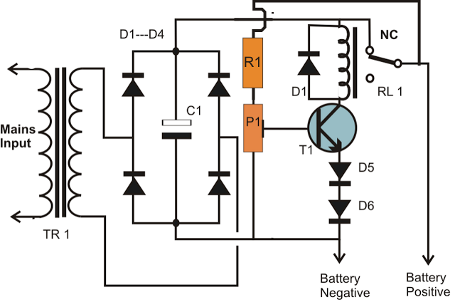
simplest smf automotive battery charger
A simple battery charger circuit is described, utilizing a single transistor for voltage detection and automatically disconnecting the battery from the supply when fully charged. The circuit's high voltage trip point is set to switch off the charging voltage when...