


Finding an Electrical Short
#electrical short
#wiring
#automotive
#Mustang
#troubleshooting
#repair
#diagnostics
#electrical problems
#wire exposure
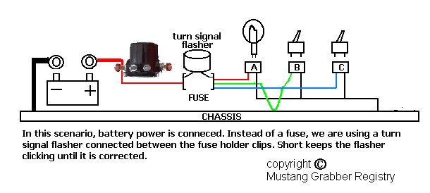
Description: Over time, various factors can lead to electrical issues in a Mustang. Components may become old and worn, or a wire might rub against something, exposing it to metal. Instances have been observed where body shops inadvertently crimp wires during body panel installations. Additionally, wiring can become obstructed during mechanical repairs, which is unfortunate since the wiring system of a Mustang functions as its nervous system. If the wiring is compromised, the vehicle's systems may not operate correctly, potentially leading to severe consequences such as electrical fires. One common issue is an electrical short. This document will explore the nature of a short circuit and methods for locating it.
Current typically flows from the battery's positive cable to the starter solenoid, through the main wiring harness, back to the dashboard, through a fuse, to an electrical device, and finally to ground, which can be the vehicle's metal body or a ground wire connected to the body. An electrical short occurs when current flows from the battery directly to the chassis or metal, which acts as a direct ground, allowing full, unchecked amperage. This creates a "short circuit" since the current has taken a shortcut to ground. If a wire shorts to ground without passing through a fuse, it can become extremely hot and burn through within seconds. Conversely, if a short occurs in a fused circuit, the fuse will heat up and quickly melt, breaking the circuit and protecting the wiring. When a fuse blows, it indicates a problem that must be addressed. It is critical to avoid using makeshift solutions, such as wrapping a blown fuse in metal, as this can lead to overheating wires, causing further damage or an electrical fire. If a fuse is blowing, the underlying issue must be identified and rectified.
To locate a short circuit, effective tools include a wiring schematic specific to the Mustang model and a self-powered test light or continuity tester. A self-powered test light functions similarly to a standard test light for checking voltages, but it operates with the battery disconnected. It features its own small battery and illuminates when it detects a wire in contact with ground. The tool has a sharp probe for piercing wire insulation and an alligator clip for grounding the test light to a metal body or dash. The recommended method begins with disconnecting both battery cables and removing the blown fuse. Using the wiring schematic, identify the components protected by the circuit. Each component will have a color-coded power wire, typically accompanied by a black ground wire. Disconnect the connectors from each component, and if a light bulb is present, remove it from its socket. Ground the test light by attaching the alligator clip to a bare metal part of the body or chassis. At each component connector or socket, employ the test light to check the power wire or connector contact. If the probe lights upon contact with the power wire, it indicates that the wire is shorting to ground, pinpointing the issue.Over time, many things can cause electrical problems with your Mustang. Components will get old and worn or a wire can rub against something and expose the wire to metal. I have seen where a body shop will inadvertently crimp a wire when they install a body panel. Sometimes, when mechanical repair is done, the wiring just gets in their way. This i s unfortunate because the wiring of your Mustang is it`s nervous system. If it isn`t in good shape, then things won`t work properly. In the worst case, this can cause an electrical fire. One condition that can cause problems is an electrical short. Let`s examine what a short is and then how to find it. Current normally flows from the battery positive cable, to the starter solenoid, through the main wiring harness back into the dash, through a fuse, then to an electrical device, and then to ground, which is either the metal body somewhere or a ground wire in the wiring harness that attaches to the body. An electrical short is where current flows from the battery, and then somewhere directly to the body chassis or metal which is a direct ground and full unchecked amperage.
Since current flows from the battery then direct to ground, it has taken a "short" cut to ground thus creating an electrical "short circuit". If a wire is shorting to ground without going through a fuse, it will get extremely hot and burn through if current flows long enough, sometimes taking only a few seconds.
If a short exists on a fused circuit, then the fuse gets too hot and quickly melts the element inside, thus breaking the circuit and protecting the wires of that circuit. When a fuse blows for any reason, then obviously there is a problem. Be happy that the fuse is doing it`s job and giving up it`s life for the cause, otherwise wires can melt or, even worse, an electrical fire can occur.
Whenever a circuit is blowing a fuse, DO NOT use anything like a fuse wrapped in metal gum wrapper or other technique that would keep current flowing through that circuit. This would cause the wire to get too hot and possibly take some other wire with it when it melts and cause more problems than you originally started with.
If a fuse is blowing, there is a reason and the cause needs to be found and corrected. To locate a short, the best tools are a wiring schematic of your year of Mustang and a self-powered test light, or continuity tester. A self-powered test light is similar to a test light to check voltages but is used with battery power disconnected.
It has it`s own small battery and light and lights up when it detects a wire that is touching ground somewhere. It has a sharp probe on one end to pierce wire insulation to get to the wire if needed and an alligator clip on a wire at the other end.
The alligator clip attaches to the metal body or dash somewhere to ground the test light. Here is the method I use and prefer because battery power is disconnected. The first thing is disconnect both battery cables at the battery and remove the fuse that is blowing. Using the wiring schematics, determine what components are on the circuit that fuse protects. Each component will have a color coded wire for power and in most cases a black wire for ground. Unplug the connectors from each component. If one of the components is a light bulb then remove the bulb from the socket. Ground the test light by attaching the alligator clip to a bare metal part of the body or chassis. At each component connector or socket, use the test light to check the power wire or connector contact that power wire feeds.
If the test probe lights when it touches the power wire, then that wire is shorting direct to ground somewhere and you have found your problem.
Current typically flows from the battery's positive cable to the starter solenoid, through the main wiring harness, back to the dashboard, through a fuse, to an electrical device, and finally to ground, which can be the vehicle's metal body or a ground wire connected to the body. An electrical short occurs when current flows from the battery directly to the chassis or metal, which acts as a direct ground, allowing full, unchecked amperage. This creates a "short circuit" since the current has taken a shortcut to ground. If a wire shorts to ground without passing through a fuse, it can become extremely hot and burn through within seconds. Conversely, if a short occurs in a fused circuit, the fuse will heat up and quickly melt, breaking the circuit and protecting the wiring. When a fuse blows, it indicates a problem that must be addressed. It is critical to avoid using makeshift solutions, such as wrapping a blown fuse in metal, as this can lead to overheating wires, causing further damage or an electrical fire. If a fuse is blowing, the underlying issue must be identified and rectified.
To locate a short circuit, effective tools include a wiring schematic specific to the Mustang model and a self-powered test light or continuity tester. A self-powered test light functions similarly to a standard test light for checking voltages, but it operates with the battery disconnected. It features its own small battery and illuminates when it detects a wire in contact with ground. The tool has a sharp probe for piercing wire insulation and an alligator clip for grounding the test light to a metal body or dash. The recommended method begins with disconnecting both battery cables and removing the blown fuse. Using the wiring schematic, identify the components protected by the circuit. Each component will have a color-coded power wire, typically accompanied by a black ground wire. Disconnect the connectors from each component, and if a light bulb is present, remove it from its socket. Ground the test light by attaching the alligator clip to a bare metal part of the body or chassis. At each component connector or socket, employ the test light to check the power wire or connector contact. If the probe lights upon contact with the power wire, it indicates that the wire is shorting to ground, pinpointing the issue.Over time, many things can cause electrical problems with your Mustang. Components will get old and worn or a wire can rub against something and expose the wire to metal. I have seen where a body shop will inadvertently crimp a wire when they install a body panel. Sometimes, when mechanical repair is done, the wiring just gets in their way. This i s unfortunate because the wiring of your Mustang is it`s nervous system. If it isn`t in good shape, then things won`t work properly. In the worst case, this can cause an electrical fire. One condition that can cause problems is an electrical short. Let`s examine what a short is and then how to find it. Current normally flows from the battery positive cable, to the starter solenoid, through the main wiring harness back into the dash, through a fuse, then to an electrical device, and then to ground, which is either the metal body somewhere or a ground wire in the wiring harness that attaches to the body. An electrical short is where current flows from the battery, and then somewhere directly to the body chassis or metal which is a direct ground and full unchecked amperage.
Since current flows from the battery then direct to ground, it has taken a "short" cut to ground thus creating an electrical "short circuit". If a wire is shorting to ground without going through a fuse, it will get extremely hot and burn through if current flows long enough, sometimes taking only a few seconds.
If a short exists on a fused circuit, then the fuse gets too hot and quickly melts the element inside, thus breaking the circuit and protecting the wires of that circuit. When a fuse blows for any reason, then obviously there is a problem. Be happy that the fuse is doing it`s job and giving up it`s life for the cause, otherwise wires can melt or, even worse, an electrical fire can occur.
Whenever a circuit is blowing a fuse, DO NOT use anything like a fuse wrapped in metal gum wrapper or other technique that would keep current flowing through that circuit. This would cause the wire to get too hot and possibly take some other wire with it when it melts and cause more problems than you originally started with.
If a fuse is blowing, there is a reason and the cause needs to be found and corrected. To locate a short, the best tools are a wiring schematic of your year of Mustang and a self-powered test light, or continuity tester. A self-powered test light is similar to a test light to check voltages but is used with battery power disconnected.
It has it`s own small battery and light and lights up when it detects a wire that is touching ground somewhere. It has a sharp probe on one end to pierce wire insulation to get to the wire if needed and an alligator clip on a wire at the other end.
The alligator clip attaches to the metal body or dash somewhere to ground the test light. Here is the method I use and prefer because battery power is disconnected. The first thing is disconnect both battery cables at the battery and remove the fuse that is blowing. Using the wiring schematics, determine what components are on the circuit that fuse protects. Each component will have a color coded wire for power and in most cases a black wire for ground. Unplug the connectors from each component. If one of the components is a light bulb then remove the bulb from the socket. Ground the test light by attaching the alligator clip to a bare metal part of the body or chassis. At each component connector or socket, use the test light to check the power wire or connector contact that power wire feeds.
If the test probe lights when it touches the power wire, then that wire is shorting direct to ground somewhere and you have found your problem.
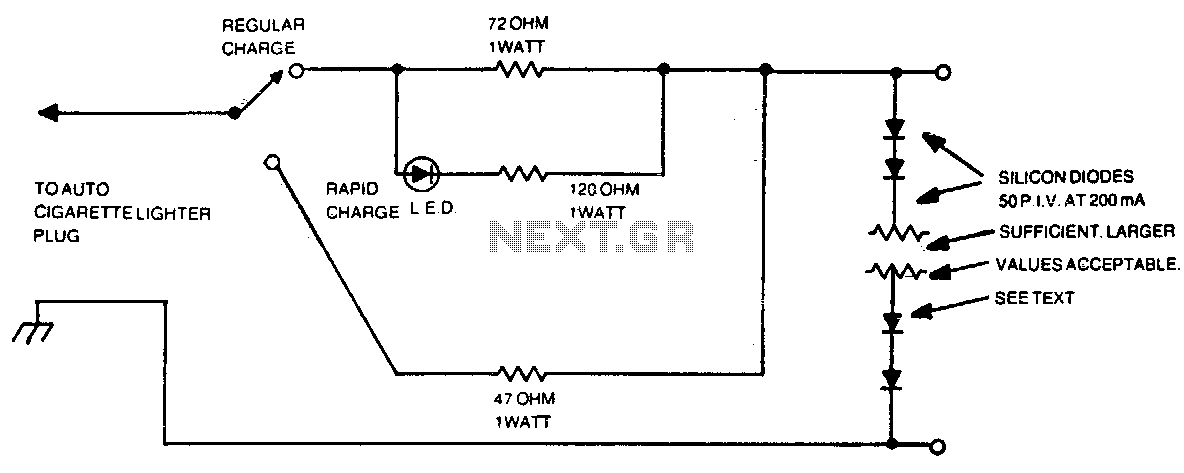
Automotive charger for ni-cad battery packs
The number of silicon diodes across the output is determined by the voltage of the battery pack. Each diode is considered at 0 volts. For example, a 10-volt pack would require 10/0 = 157, or 16 diodes.
In the context of...

Voltage Regulator For Cars And Motorcycles
This regulator circuit can be used on an alternator that has one field terminal grounded. When the input voltage becomes too high, Q1 conducts, and the base of Q2 is driven toward ground, reducing the voltage fed to Q3. This...
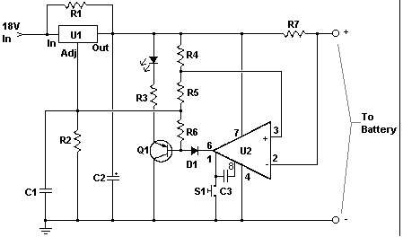
Car battery charger Automative car and motorcycle schematics
The circuit is designed to operate with an external power supply, which is why it does not include a transformer, rectifier, or filter capacitors in the schematic. However, these components can be added if desired. To utilize the circuit, connect...
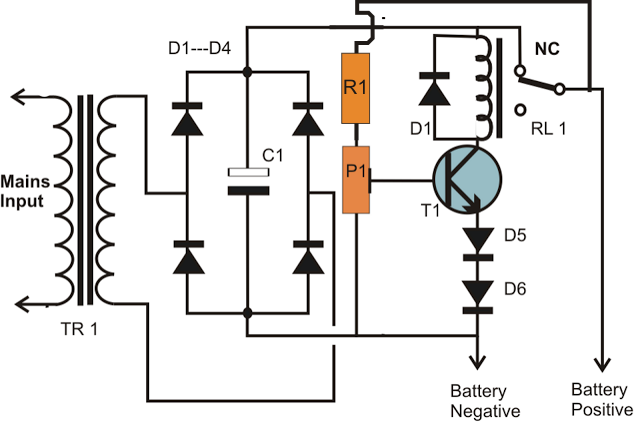
simplest smf automotive battery charger
A simple battery charger circuit is described, utilizing a single transistor for voltage detection and automatically disconnecting the battery from the supply when fully charged. The circuit's high voltage trip point is set to switch off the charging voltage when...
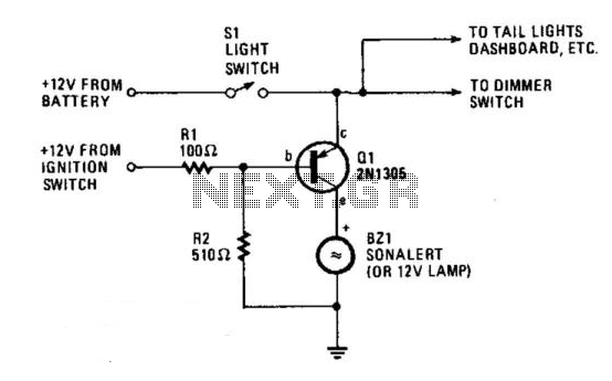
Automobile Lights-On Reminder
The circuit provides a visible or audible warning when the headlights are on. It utilizes a 2N1305 transistor as a switch to activate either a Sonalert tone generator or a small 12-V lamp. The operating current for the transistor is...
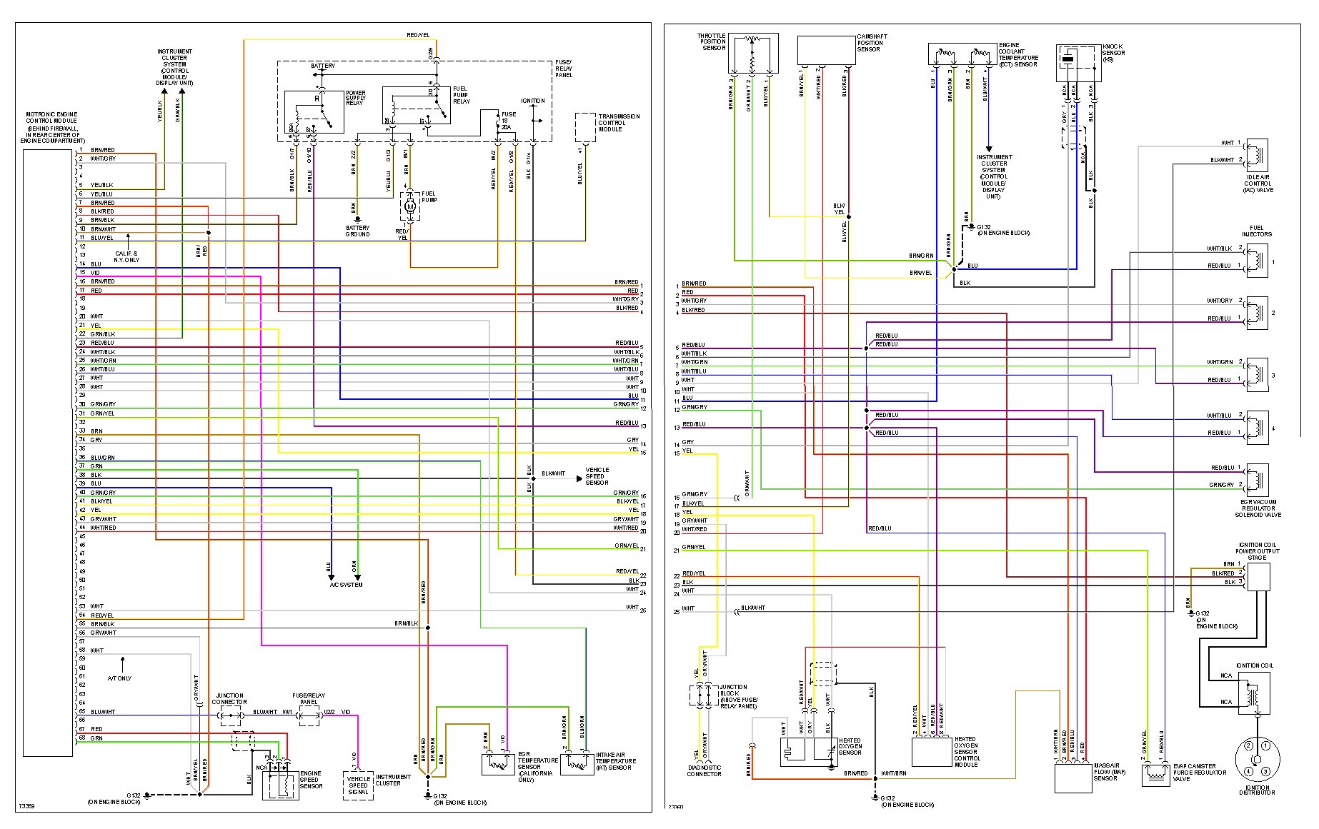
1994 Golf GTI wiring
I have purchased and sold 10 MK3 Jettas and 1 MK3 Golf. This is my first time posting on a forum. I paid $400 for a 1994 GTI with the intention of fixing it and reselling it. The car was...
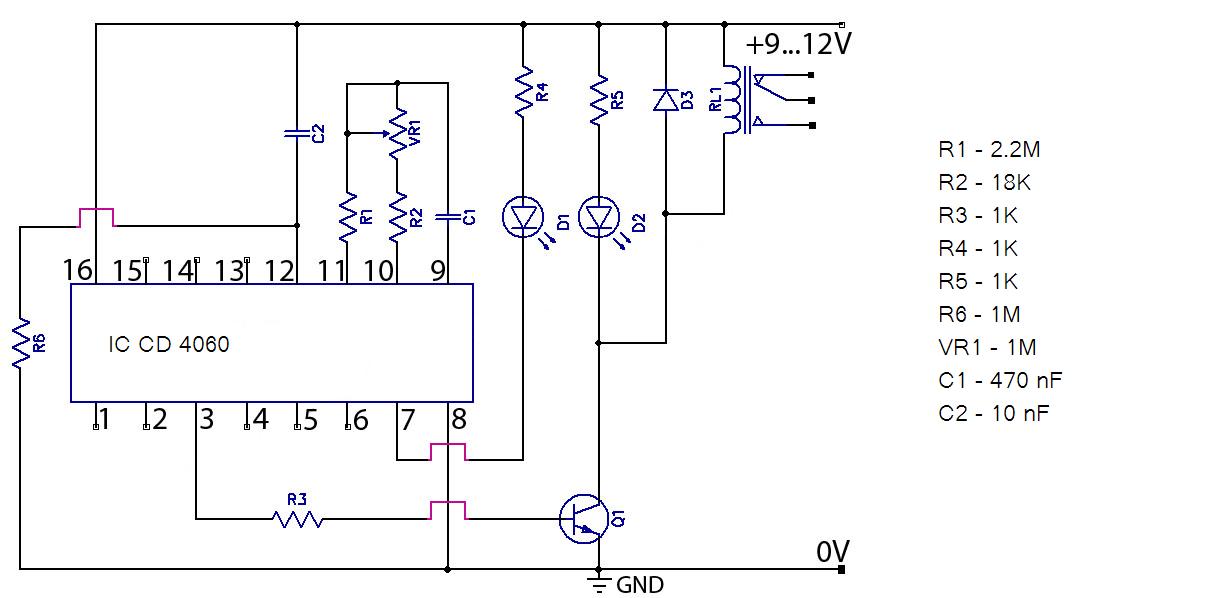
CIRCUIT IS NOT WORKING
Hello everyone, please examine this circuit. I constructed it recently, but it is not functioning. I have verified all connections and components, and everything appears to be in order. However, when I power it on...
The circuit in question appears to...
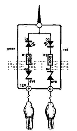
Automotive Electrical Tester
This compact tester is designed for checking vehicle electrical circuits. Two LEDs indicate whether one of the clips is connected to the positive supply line (red) or to ground (green). The unit is powered by the vehicle battery. It is...
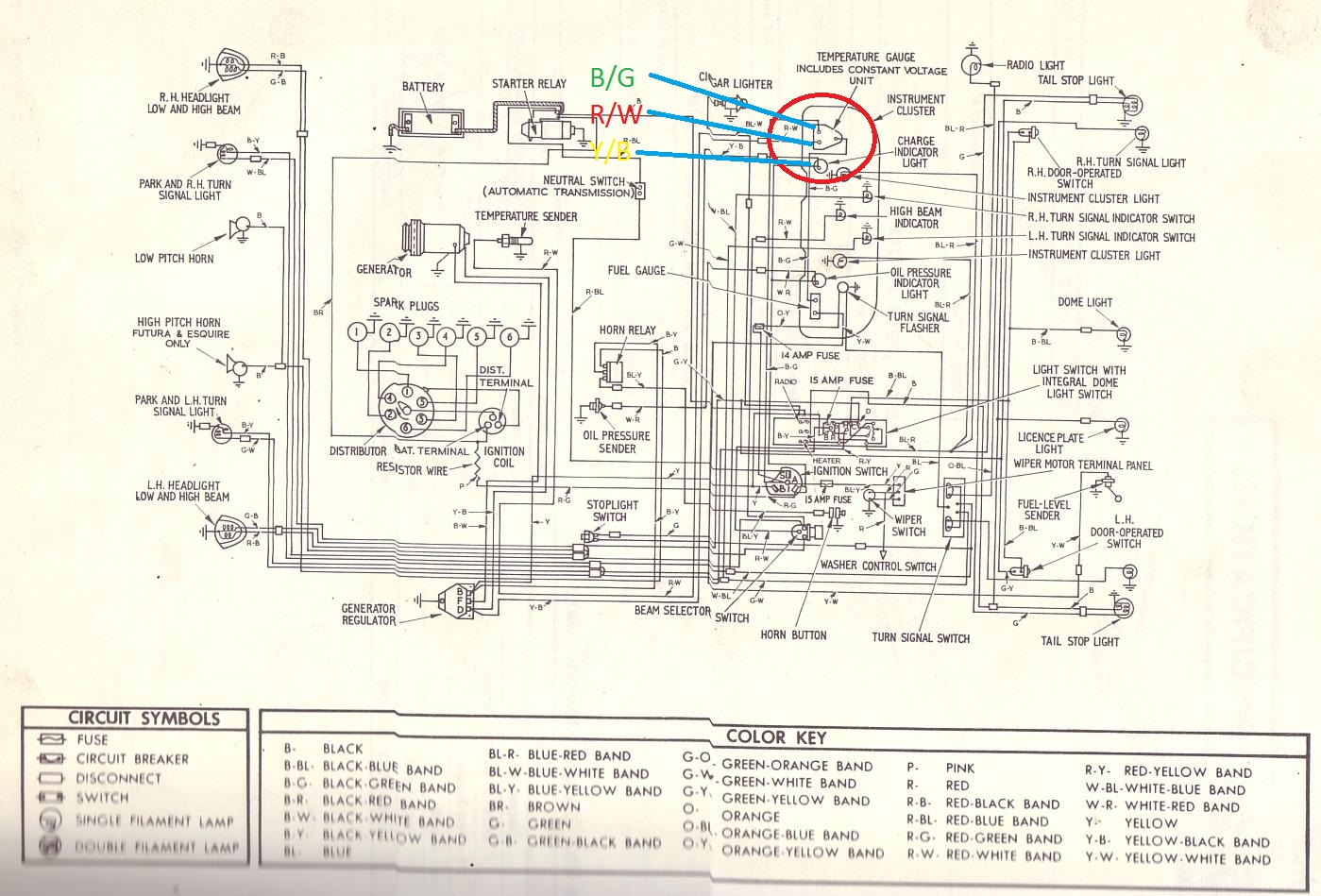
1964 xm
I am wiring up my 1964 XM and am unsure where the wires connect for the temperature gauge. On the back of the gauge, there are labels I, S, and A. The wires are colored Green/Black, Red/White, and Yellow/Blue. Do...