


gps tracker project gps module jp module lcd dispaly
#GPS tracker
#GPS module
#JP module
#LCD display
#BasicStamp 2P
#PIC chip
#data logging
#MMC/SD card
#latitude
#longitude
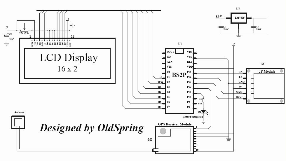
Description: A GPS tracker demonstration program with data logging capability. It utilizes a BasicStamp 2P (or alternatively, a PIC chip) to interface with a GPS module, a JP module, and a 16x2 LCD display. The sample code employed is standard PBasic 2.5, which can be easily adapted to PicBasic or PicBasic Pro. This program can record GPS data onto an MMC/SD card, capturing latitude and longitude information. The recorded data can be processed using Google Maps on the website. If Google Earth is installed, the data can also be converted into a KML file format, suitable for Google Earth.
The project involves assembling various components, including the GPS module, microcontroller, and display, according to the provided schematic. After connecting the components, the code must be uploaded to the microcontroller for the system to function correctly. The GPS module outputs several data strings per second, including the essential RMC string, which provides the necessary positional information. The standard output rate is 4800 baud. The GPS module operates at 3V serial levels, which can be directly connected to the USART receive input on a PIC microcontroller. Configuring the USART to 4800 baud, with 8 data bits and 1 stop bit, allows for the reception of each character, which the code subsequently processes.
To successfully create a GPS tracking module, knowledge in several areas is essential. This includes understanding microcontroller programming, interfacing with serial communication protocols, and familiarity with GPS technology and its data formats. Students should also be adept at reading datasheets for components and troubleshooting potential issues during assembly and coding. Building a GPS module from scratch is a complex task that typically requires advanced skills and access to specialized equipment. It is advisable to utilize commercial GPS modules to simplify the development process while still achieving the desired functionality.A GPS tracker demonstration program with data logging capacity. It uses BasicStamp 2P (also you can use PIC chip) to interface with a GPS Module, JP Module and 16x2 LCD display. Sample code used is standard PBasic 2. 5 ( It can be changed to PicBasic or PicBasic Pro very easy). It can record GPS data to a MMC/SD card with latitude and longitude information. The data can be processed from Google Map at the website:. If you have Google Earth installed, the data also can be processed into a KML file (Google earth data file format) at the website: hi. u know what. ur project would be very helpful to me. coz we have been given the same project for our final year. but the problem is. i have been told to make the module of GPS myself. now can you pz let me know as to what all things may be necessary to study to make this possible. and whethr it is possible to be made on our own. plz reply soon. thanx. tc I think I have already posted all of information ( including manufactures and parts datasheet) for this project.
You can follow the project schematic put every parts togather, load the code to MCU. It should work. hi. u know what. ur project would be very helpful to me. coz we have been given the same project for our final year. but the problem is. i have been told to make the module of GPS myself. now can you pz let me know as to what all things may be necessary to study to make this possible. and whethr it is possible to be made on our own. plz reply soon. thanx. tc What do you have at your disposal In all likelihood you do not have the capability to build it yourself without using a GPS module. The 2GHz satellite signal is far beyond the ability of many engineers, never mind students, even with the appropriate ICs in hand.
Unless you have a $10K+ prototyping system capable of double sided plate through PCBs and are capable and willing to solder 0. 5mm pitch 100 pin ICs for 5-10 prototype runs to work out the bugs do not even bother. All GPS receivers that I have used will output several strings each second. All you need to do is apply power to the GPS receiver and the data strings start being sent. One of those is the RMC string which tells you all you usually need for position. The usual rate is 4800 baud. If you can connect to the 3 V serial level from the GPS, that can be connected directly to the USART receive input on a PIC.
If you set the USART to 4800 baud, 8 bits, 1 stop bit, it should receive each character, and then the code takes each character from the USART.
The project involves assembling various components, including the GPS module, microcontroller, and display, according to the provided schematic. After connecting the components, the code must be uploaded to the microcontroller for the system to function correctly. The GPS module outputs several data strings per second, including the essential RMC string, which provides the necessary positional information. The standard output rate is 4800 baud. The GPS module operates at 3V serial levels, which can be directly connected to the USART receive input on a PIC microcontroller. Configuring the USART to 4800 baud, with 8 data bits and 1 stop bit, allows for the reception of each character, which the code subsequently processes.
To successfully create a GPS tracking module, knowledge in several areas is essential. This includes understanding microcontroller programming, interfacing with serial communication protocols, and familiarity with GPS technology and its data formats. Students should also be adept at reading datasheets for components and troubleshooting potential issues during assembly and coding. Building a GPS module from scratch is a complex task that typically requires advanced skills and access to specialized equipment. It is advisable to utilize commercial GPS modules to simplify the development process while still achieving the desired functionality.A GPS tracker demonstration program with data logging capacity. It uses BasicStamp 2P (also you can use PIC chip) to interface with a GPS Module, JP Module and 16x2 LCD display. Sample code used is standard PBasic 2. 5 ( It can be changed to PicBasic or PicBasic Pro very easy). It can record GPS data to a MMC/SD card with latitude and longitude information. The data can be processed from Google Map at the website:. If you have Google Earth installed, the data also can be processed into a KML file (Google earth data file format) at the website: hi. u know what. ur project would be very helpful to me. coz we have been given the same project for our final year. but the problem is. i have been told to make the module of GPS myself. now can you pz let me know as to what all things may be necessary to study to make this possible. and whethr it is possible to be made on our own. plz reply soon. thanx. tc I think I have already posted all of information ( including manufactures and parts datasheet) for this project.
You can follow the project schematic put every parts togather, load the code to MCU. It should work. hi. u know what. ur project would be very helpful to me. coz we have been given the same project for our final year. but the problem is. i have been told to make the module of GPS myself. now can you pz let me know as to what all things may be necessary to study to make this possible. and whethr it is possible to be made on our own. plz reply soon. thanx. tc What do you have at your disposal In all likelihood you do not have the capability to build it yourself without using a GPS module. The 2GHz satellite signal is far beyond the ability of many engineers, never mind students, even with the appropriate ICs in hand.
Unless you have a $10K+ prototyping system capable of double sided plate through PCBs and are capable and willing to solder 0. 5mm pitch 100 pin ICs for 5-10 prototype runs to work out the bugs do not even bother. All GPS receivers that I have used will output several strings each second. All you need to do is apply power to the GPS receiver and the data strings start being sent. One of those is the RMC string which tells you all you usually need for position. The usual rate is 4800 baud. If you can connect to the 3 V serial level from the GPS, that can be connected directly to the USART receive input on a PIC.
If you set the USART to 4800 baud, 8 bits, 1 stop bit, it should receive each character, and then the code takes each character from the USART.
C-Bot Article
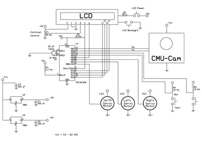
The schematic is illustrated in figure 10. The circuit can be hardwired onto a breadboard, or a printed circuit board (PCB) can be purchased, as shown in figure 11. The LCD display utilized is a 2-line by 16-character display. An...
Large Lcd Display Buffering Driver Circuit
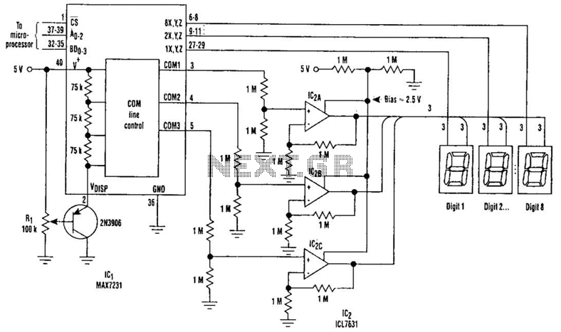
Large LCD devices with one or more displays exhibit significant driving capacitance to the driver circuits. To address this issue, the drive circuit incorporates a buffer amplifier for each of the three common lines. Each amplifier can be programmed independently...
8 digital LCD display driver circuit
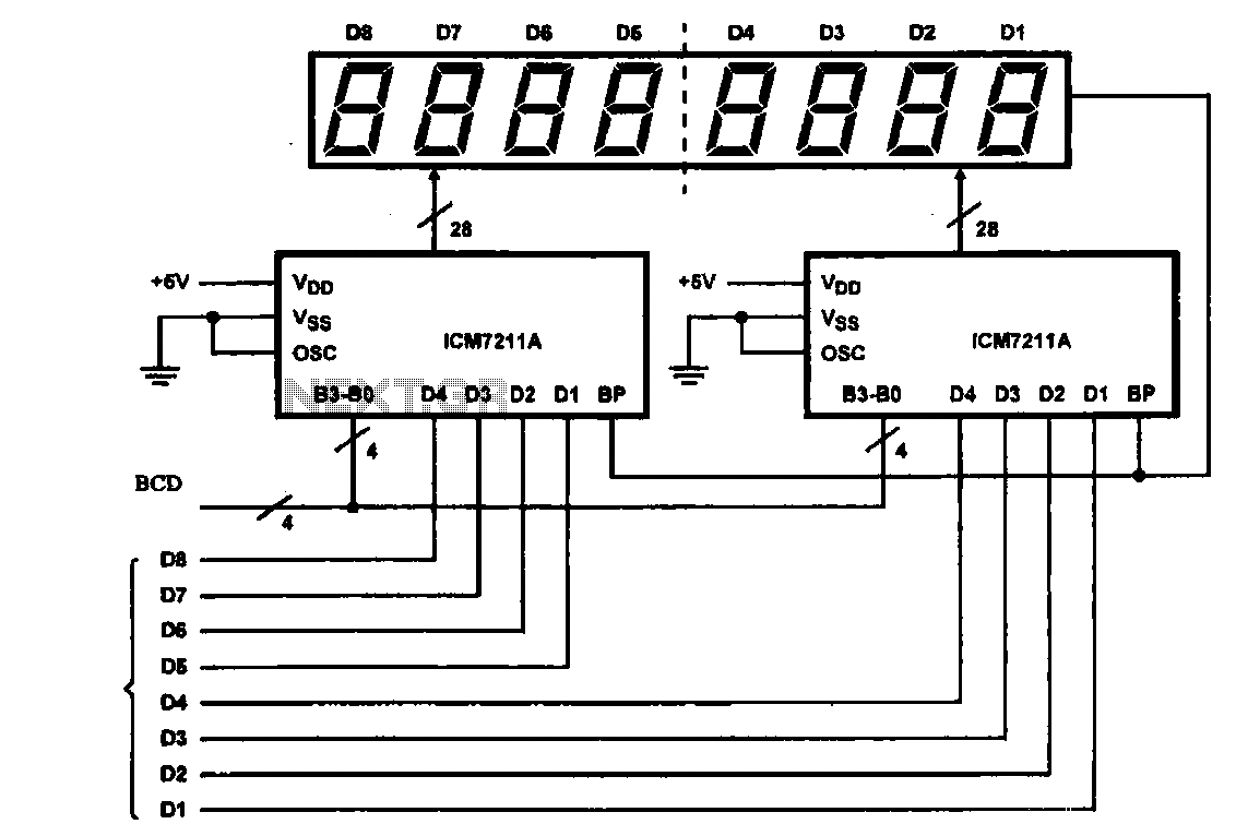
This circuit illustrates an 8-digit digital tube display driver, utilizing two ICM7211A integrated circuits. A BCD (Binary-Coded Decimal) to binary data signal is transmitted to the BO-B3 pins of the ICM7211A. The digital signals are divided into two groups and...
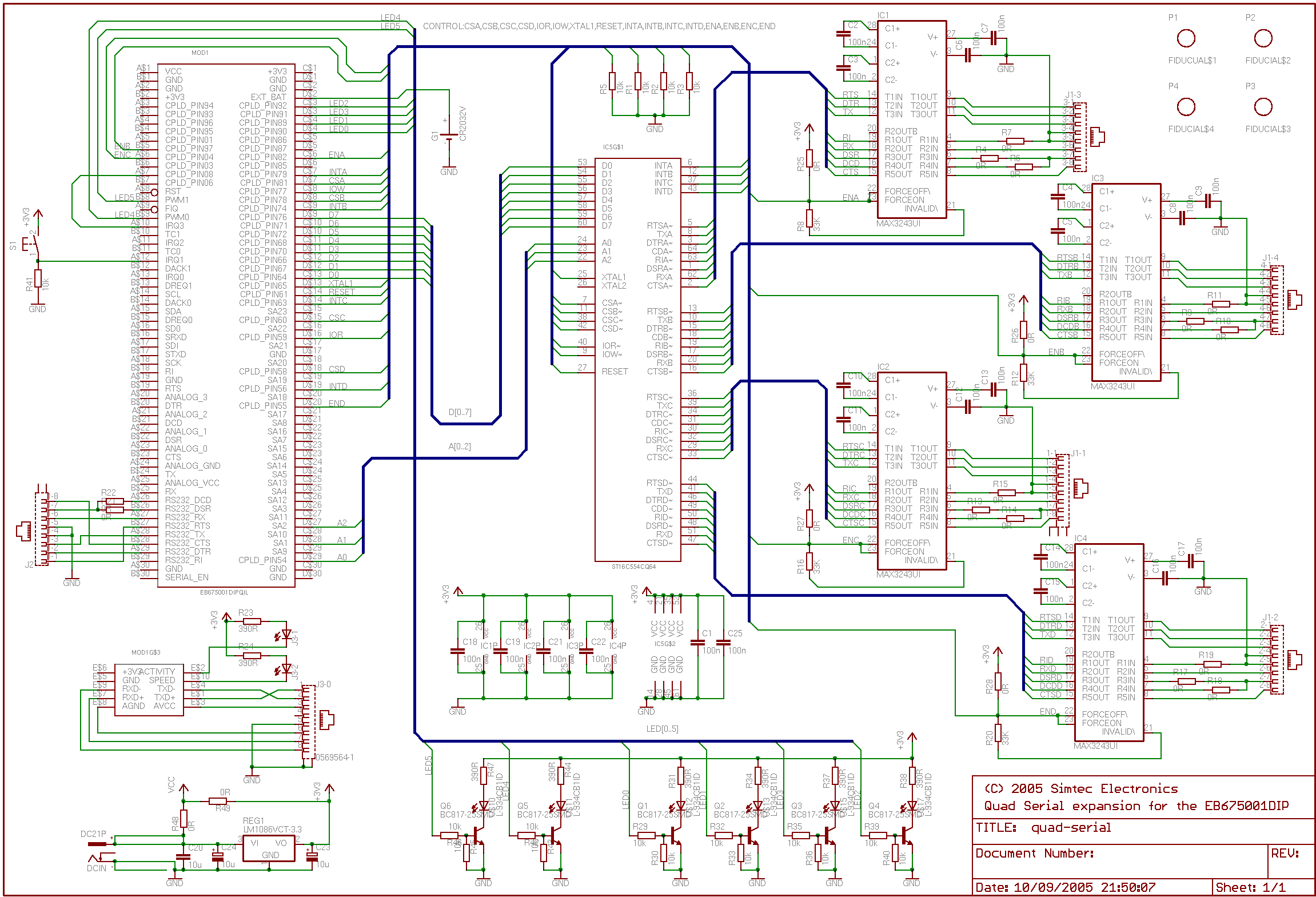
Attaching a GPS module to the EB675001DIP
The CPLD in this design is utilized solely for interfacing with the LCD module, employing the same code as outlined in the application note for connecting an LCD module to the EB675001DIP. Communication with the GPS module is facilitated through...
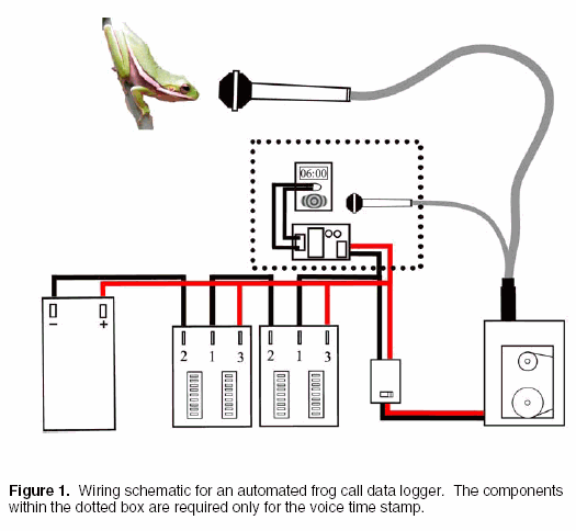
remote field recorders automated frog call data loggers
Automated frog call data loggers have been effectively utilized to gather information on: (1) species presence during sampling, enabling the reliable recording of species that may be overlooked due to time constraints; (2) life history and phenology details, such as...
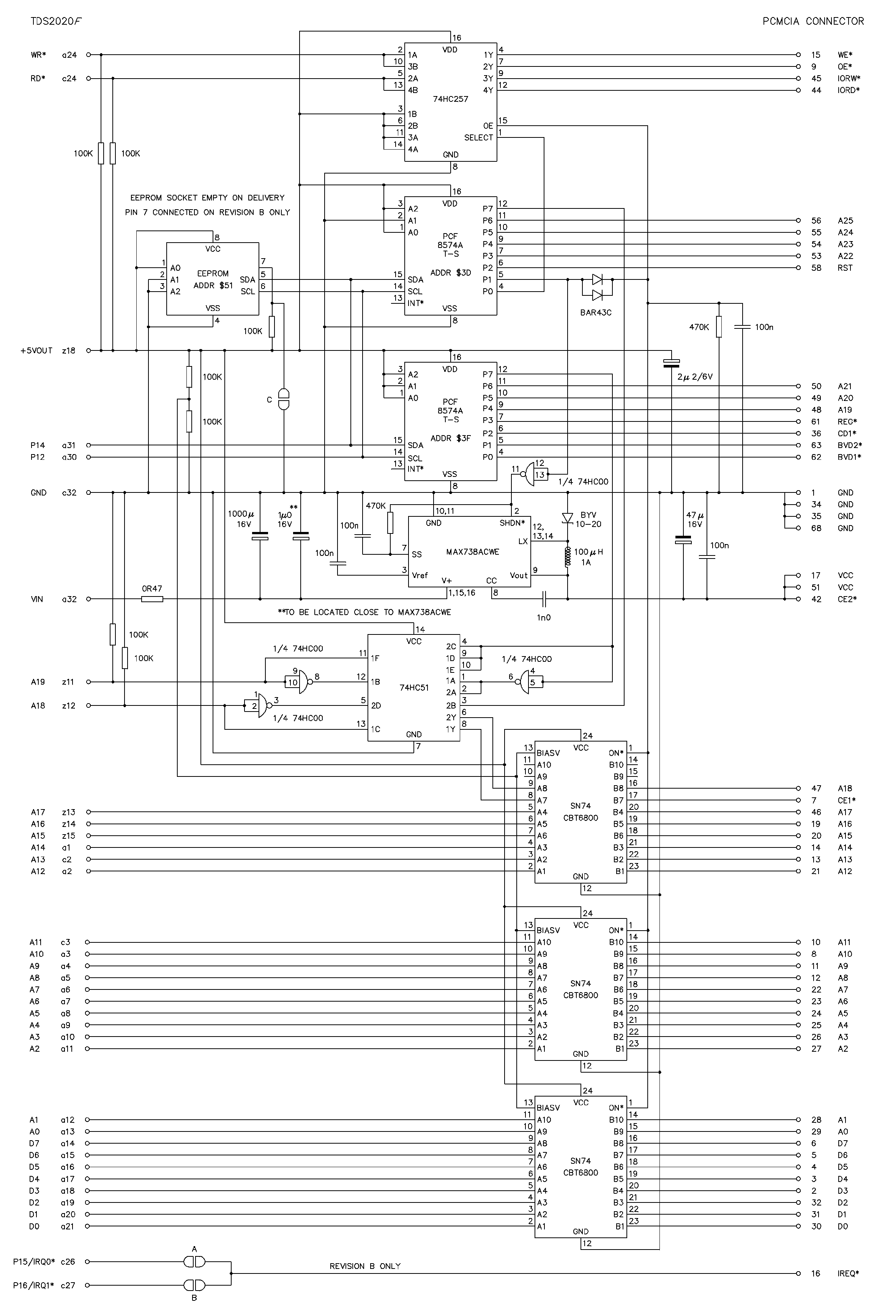
Data logging to Compact Flash and PCMCIA TDS2020F
This section discusses Compact Flash, Flash-ATA, and hard disks. For additional media, refer to DATA LOGGING TO RAM CARDS on page 274 and DATA LOGGING TO FLASH AND RAM CHIPS on page 279. This module enables the rapid creation of...
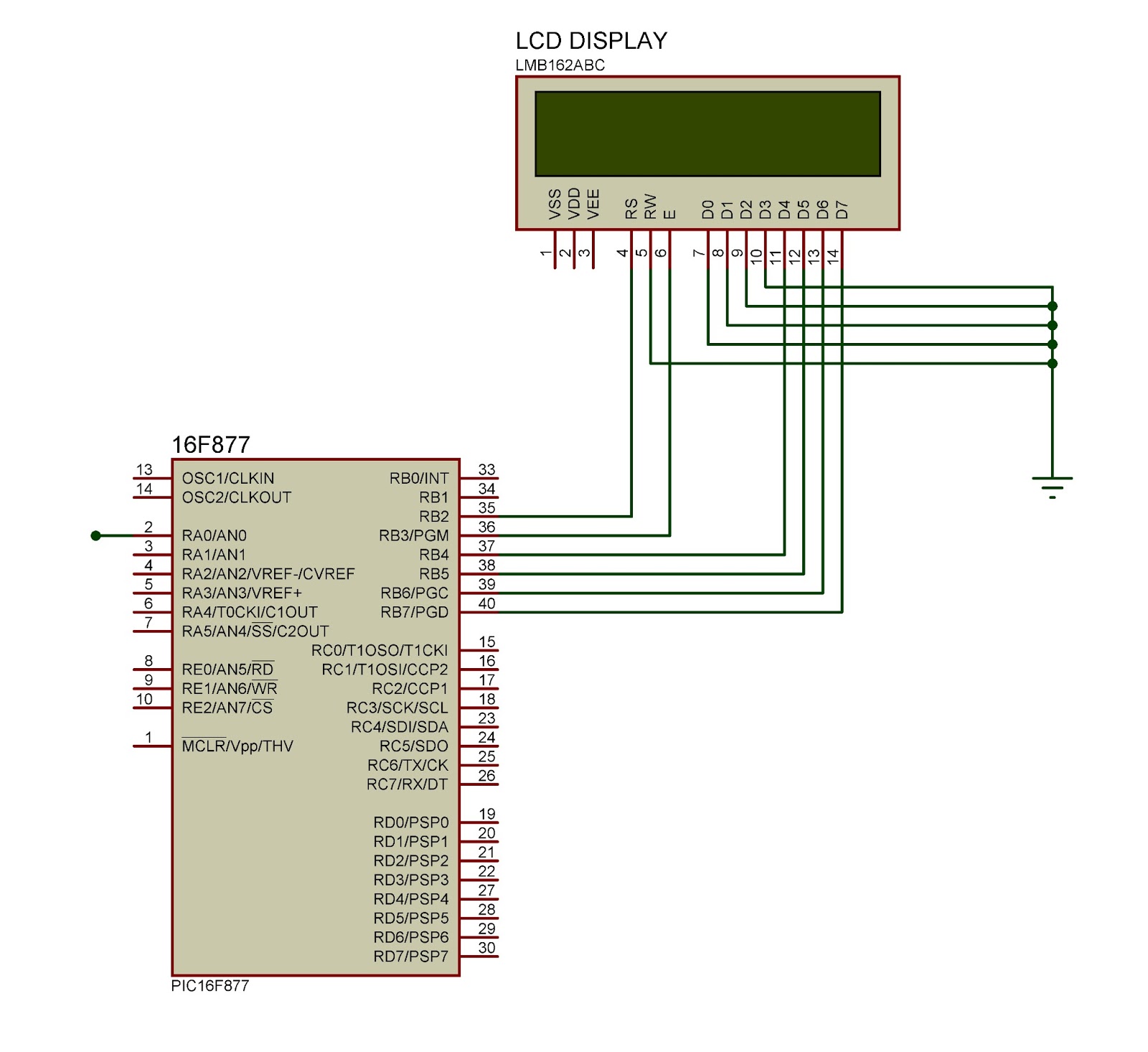
LCD Display with Microcontroller
This document outlines the connection of a 16x2 LCD display to a microcontroller, specifically the PIC 16F877A. The circuit diagram is provided, although power supply and oscillator connections for both the PIC and LCD are not depicted. The LCD typically...
NAD C 520
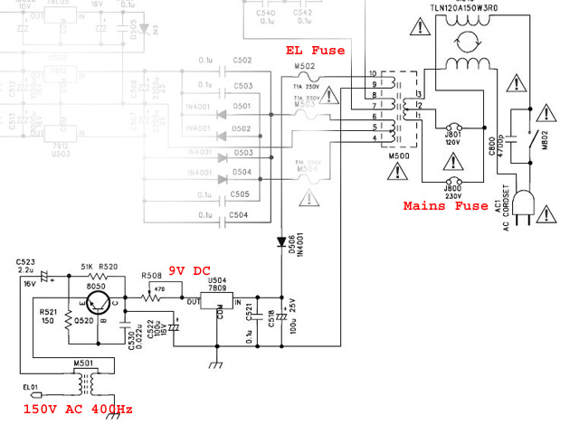
The LCD display on the NAD C520 compact disc player has become unreadable. The audio and CD deck are functioning properly, but operating the unit without a legible display is challenging. When viewed under the right lighting, the basic LCD...
TTL pulse recording for fMRI data collection
This web page outlines the installation and usage of ezlog data logging software. This software enables the measurement of the timing of various events, facilitating synchronization of different stimuli. Specifically, the software is designed to provide a detailed report on...