


High pressure natural gas shutoff valve drive circuit diagram
#natural gas
#shutoff valve
#solid state relay
#driver circuit
#dual-fuel
#high pressure
#gas valve
#engine control
#safety
#valve drive
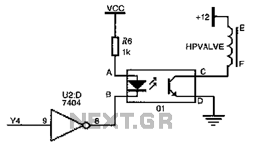
Description: The driver circuit for the high-pressure natural gas shut-off valve utilizes solid-state relays. In dual-fuel mode operation, the fuel switching mechanism is controlled by a logic section that activates Y4 to a high state via U2 (7404 inverters). This causes point B (UB) to be low, while the surface potential at point A (UA) is higher than point B. Consequently, the input of the solid-state relay is energized, resulting in the activation of the output terminal. When connected, the output of the circuit applies a 12V working voltage to the solenoid valve (HPVALVE), allowing high-pressure natural gas to enter the engine after passing through the pressure reducer valve. If the logic section issues a command to close the electromagnetic valve, Y4 is set to low. After inversion, point B becomes high, and the potential at points A and B equalizes, preventing input current through the solid-state relay and deactivating the output terminal. The solenoid valve then returns to its normally closed position due to spring force.
The driver circuit for the high-pressure natural gas shut-off valve is designed to manage the flow of natural gas in a dual-fuel engine operation. The circuit employs solid-state relays for reliable switching, minimizing mechanical wear and improving response times. The operational logic is dictated by a series of inverters (U2, specifically 7404), which play a critical role in signal processing.
In the active state, when the fuel switching mechanism is engaged, the logic section outputs a high signal to Y4, which allows the solid-state relay to conduct. This conduction enables the output terminal to provide a 12V supply to the solenoid valve (HPVALVE). The solenoid valve is critical for controlling the gas flow into the engine, ensuring that it only receives gas that has been properly regulated by the pressure reducer valve.
The circuit's design incorporates fail-safe features. When the logic section determines that the electromagnetic valve should close, it sets Y4 to a low state. The inverter then processes this signal, resulting in point B being driven high. This change in state effectively cuts off current to the solid-state relay, deactivating the output terminal and allowing the solenoid valve to return to its default closed position, aided by a spring mechanism. This ensures that in the event of a fault or loss of control signal, the gas flow is automatically halted, enhancing safety during operation.
Overall, this circuit is a robust solution for managing high-pressure natural gas in dual-fuel applications, combining effective logic control with reliable solid-state switching to ensure safe and efficient operation. As shown for the driver circuit high pressure natural gas shut-off valve, the device 01 for the solid state relays. When the engine is in dual-fuel mode of operation, the opera tion of the fuel switching mechanism, the logic judging section instructs so Y4 1, is high by U2 (7404, inverters), the electric point B UB low, surface potential UA point a to point B than high, then the input of the solid state relay is turned on, the output terminal is also turned on. The output of CD Once connected, the solenoid valve HPVALVE ends will add 12V rated working voltage, high-pressure natural gas before the pressure reducer valve open, gas enters the engine under reduced pressure.
When the instruction issue logic portion of the electromagnetic valve is closed, Y4 0, after the inverter, B is high, UA UB, no input current through the solid state relay, the output terminal is not turned on, the solenoid valve recovery normally closed by the spring force.
The driver circuit for the high-pressure natural gas shut-off valve is designed to manage the flow of natural gas in a dual-fuel engine operation. The circuit employs solid-state relays for reliable switching, minimizing mechanical wear and improving response times. The operational logic is dictated by a series of inverters (U2, specifically 7404), which play a critical role in signal processing.
In the active state, when the fuel switching mechanism is engaged, the logic section outputs a high signal to Y4, which allows the solid-state relay to conduct. This conduction enables the output terminal to provide a 12V supply to the solenoid valve (HPVALVE). The solenoid valve is critical for controlling the gas flow into the engine, ensuring that it only receives gas that has been properly regulated by the pressure reducer valve.
The circuit's design incorporates fail-safe features. When the logic section determines that the electromagnetic valve should close, it sets Y4 to a low state. The inverter then processes this signal, resulting in point B being driven high. This change in state effectively cuts off current to the solid-state relay, deactivating the output terminal and allowing the solenoid valve to return to its default closed position, aided by a spring mechanism. This ensures that in the event of a fault or loss of control signal, the gas flow is automatically halted, enhancing safety during operation.
Overall, this circuit is a robust solution for managing high-pressure natural gas in dual-fuel applications, combining effective logic control with reliable solid-state switching to ensure safe and efficient operation. As shown for the driver circuit high pressure natural gas shut-off valve, the device 01 for the solid state relays. When the engine is in dual-fuel mode of operation, the opera tion of the fuel switching mechanism, the logic judging section instructs so Y4 1, is high by U2 (7404, inverters), the electric point B UB low, surface potential UA point a to point B than high, then the input of the solid state relay is turned on, the output terminal is also turned on. The output of CD Once connected, the solenoid valve HPVALVE ends will add 12V rated working voltage, high-pressure natural gas before the pressure reducer valve open, gas enters the engine under reduced pressure.
When the instruction issue logic portion of the electromagnetic valve is closed, Y4 0, after the inverter, B is high, UA UB, no input current through the solid state relay, the output terminal is not turned on, the solenoid valve recovery normally closed by the spring force.
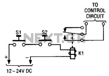
Simple Safety Circuit Circuit
The simple two-hand safety control switch consists of two pushbutton switches connected in series; both must be depressed to energize the relay.
The two-hand safety control switch is designed to enhance safety in applications where the operation of machinery or equipment...
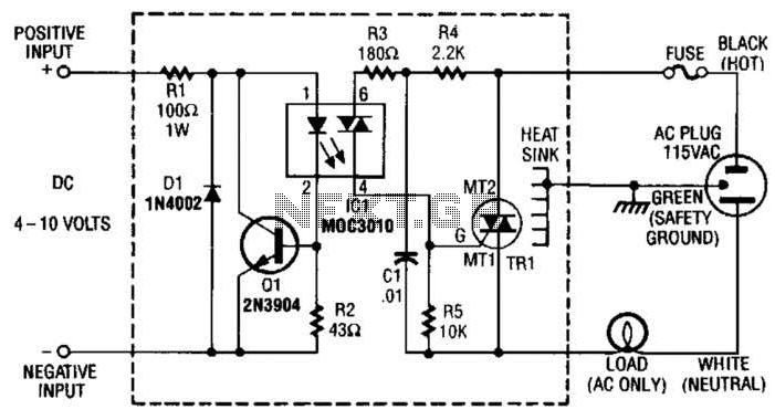
Solid State Relay Circuit Circuit
Rl limits input current while Ql acts as a current sink to protect IC1. D1 serves as a polarity protector. IC1 provides a triac output to trigger the main triac, TR1.
The circuit consists of several key components that work...
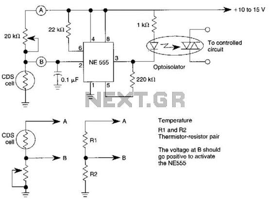
Solid State Relay circuits
This dark-activated relay switch can be utilized to activate walkway or other outdoor lighting at dusk. By employing alternate connections to points A and B, it is capable of sensing varying levels of illumination, as well as high and low...
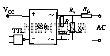
AC-SSR application circuit
This document discusses the AC solid-state relay (AC-SSR) and presents its basic application circuit as illustrated in Figure (a). Additionally, it includes a TTL drive SSR circuit depicted in Figure (b), a CMOS driver circuit for the SSR shown in...
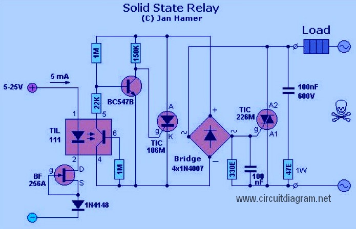
solid state relay
A Solid State Relay is not a traditional relay; it consists solely of an electronic circuit that performs the switching function. It operates similarly to a relay, allowing a low voltage to control a higher voltage, offering advantages over conventional...
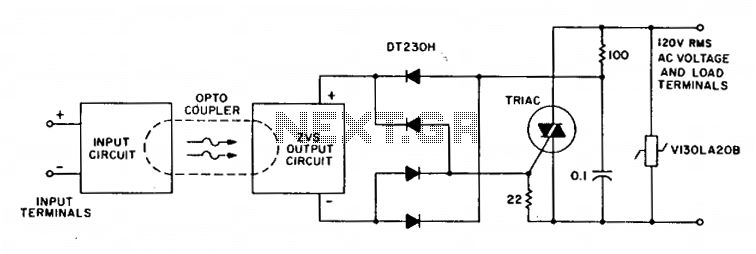
Integrated solid state relay
A complete zero-voltage switch solid-state relay consists of an input circuit, an output circuit, and a power thyristor. The circuit features a triac power thyristor with a snubber circuit and GE-MOVRII Vans for transient over-voltage protection. A 22-ohm resistor shunts...
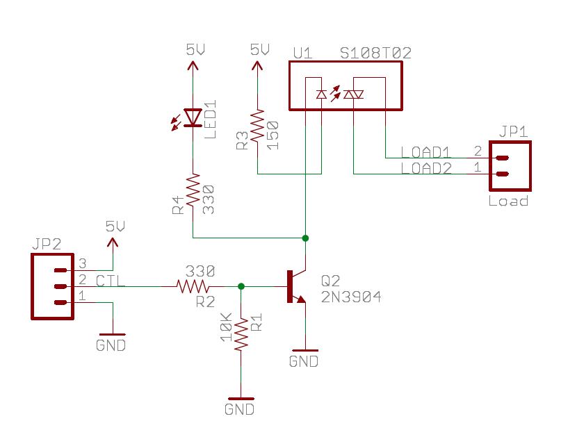
ssr breakout boards
The Sparkfun Solid State Relay (SSR) Breakout Board operates similarly to a traditional relay but utilizes semiconductors for switching. It is powered by the mbed VU 5V supply and is compatible with any mbed digital output pin. The schematic for...
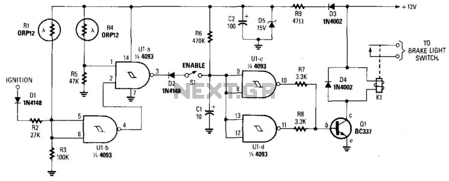
Night Safety Light For Autos
This circuit activates the brake lights of a parked car when headlights from an approaching vehicle are detected, alerting the driver of the oncoming vehicle about the stationary car. LDR4 serves as the sensor, while LDR1 deactivates the circuit by...
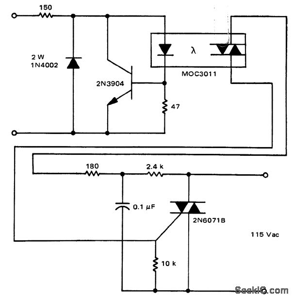
Solid state relay circuit with MOC3011 triac driver
A solid-state relay circuit features an input protection mechanism utilizing the MOC3011 triac driver. The input voltage for the protection circuit can range from 3 to 30 volts DC, as noted by Motorola Semiconductor Products Inc.
The solid-state relay (SSR) circuit...