


Ignition Coil Buzz Box circuit
#ignition coil
#556 timer
#MOSFET
#oscillator
#spark generation
#automotive electronics
#breaker points
#frequency control
#duty cycle
#IRF740
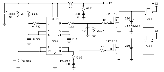
Description: This circuit creates a buzz coil using a standard automotive ignition coil. A 556 dual timer is employed to establish the frequency and duty cycle of the coil current. One timer functions as an oscillator to generate the 200 Hz rectangular waveform required to control the IRF740 MOSFET, while the second timer switches the oscillator on and off as the breaker points open and close (closed = on). The outcome is a consistent stream of sparks from the ignition coil, spaced approximately 5 milliseconds apart while the breaker points are closed.
The buzz coil circuit utilizes a standard automotive ignition coil, which is designed to transform low voltage from the vehicle's battery into a high-voltage spark necessary for igniting fuel in an engine. The core component of this circuit is the 556 dual timer, which consists of two independent timers that can be configured in various modes, including astable and monostable operations.
In this application, one of the timers is configured in astable mode to generate a continuous 200 Hz rectangular waveform. This waveform serves as the control signal for the gate of the IRF740 MOSFET, a power MOSFET capable of handling high voltages and currents. The IRF740 acts as a switch, allowing the current from the ignition coil to be rapidly turned on and off in synchronization with the generated waveform.
The second timer is configured to operate in monostable mode, where it responds to the state changes of the breaker points. When the breaker points close, the timer triggers the oscillator, allowing the MOSFET to conduct and energize the ignition coil. Conversely, when the breaker points open, the timer deactivates the oscillator, cutting off the current flow to the coil. This switching action results in the production of a series of high-voltage sparks emitted from the ignition coil, with a consistent interval of approximately 5 milliseconds between each spark while the breaker points remain closed.
The design of this circuit is particularly effective for applications requiring a high-frequency spark generation, such as in ignition systems or for creating a buzz coil effect in various electronic projects. Proper attention should be paid to the component ratings, ensuring they can handle the voltages and currents involved, particularly the MOSFET and the ignition coil, to prevent damage during operation. Additionally, adequate heat dissipation measures should be implemented for the MOSFET to maintain reliable performance during extended use.Here`s a circuit to create a buzzcoil using a standard automotive ignition coil. A 556 dual timer is used to establish the frequency and duty cycle of the coil current. One of the timers is used as an oscillator to generate the 200 Hz rectangular waveform needed to control the (IRF740 MOSFET) while the second timer switches the oscillator on and off as the breaker points open and close (closed = on). The result is a steady stream of sparks from the ignition coil spaced about 5 milliseconds apart while the breaker points are closed..
The buzz coil circuit utilizes a standard automotive ignition coil, which is designed to transform low voltage from the vehicle's battery into a high-voltage spark necessary for igniting fuel in an engine. The core component of this circuit is the 556 dual timer, which consists of two independent timers that can be configured in various modes, including astable and monostable operations.
In this application, one of the timers is configured in astable mode to generate a continuous 200 Hz rectangular waveform. This waveform serves as the control signal for the gate of the IRF740 MOSFET, a power MOSFET capable of handling high voltages and currents. The IRF740 acts as a switch, allowing the current from the ignition coil to be rapidly turned on and off in synchronization with the generated waveform.
The second timer is configured to operate in monostable mode, where it responds to the state changes of the breaker points. When the breaker points close, the timer triggers the oscillator, allowing the MOSFET to conduct and energize the ignition coil. Conversely, when the breaker points open, the timer deactivates the oscillator, cutting off the current flow to the coil. This switching action results in the production of a series of high-voltage sparks emitted from the ignition coil, with a consistent interval of approximately 5 milliseconds between each spark while the breaker points remain closed.
The design of this circuit is particularly effective for applications requiring a high-frequency spark generation, such as in ignition systems or for creating a buzz coil effect in various electronic projects. Proper attention should be paid to the component ratings, ensuring they can handle the voltages and currents involved, particularly the MOSFET and the ignition coil, to prevent damage during operation. Additionally, adequate heat dissipation measures should be implemented for the MOSFET to maintain reliable performance during extended use.Here`s a circuit to create a buzzcoil using a standard automotive ignition coil. A 556 dual timer is used to establish the frequency and duty cycle of the coil current. One of the timers is used as an oscillator to generate the 200 Hz rectangular waveform needed to control the (IRF740 MOSFET) while the second timer switches the oscillator on and off as the breaker points open and close (closed = on). The result is a steady stream of sparks from the ignition coil spaced about 5 milliseconds apart while the breaker points are closed..
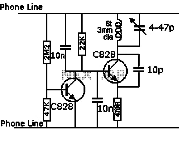
high current mosfet toggle switch
This circuit design is for a high current toggle switch, adapted from the "Toggle Switch Debounced Pushbutton" by John Lundgren. It is intended for applications where the load needs to be switched on from one location and off from another....
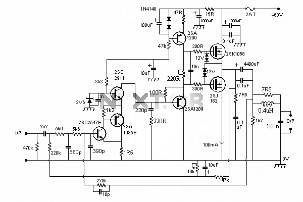
100W Mosfet Power Amplifier
In this circuit we use the 2SK1058 and the 2SJ162 Mosfets. This could be avoided by a fairly simple bootstrapping circuit, but the improvement in maximum output may be just a fraction of a dB, depending on the supply voltage...
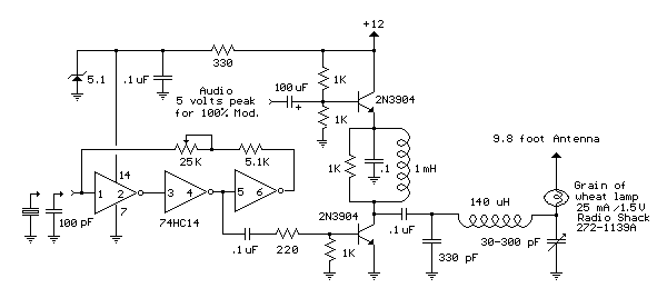
Micro Power AM Broadcast Transmitter
This circuit utilizes a 74HC14 hex Schmitt trigger inverter as a square wave oscillator to drive a small signal transistor configured in a class C amplifier setup. The frequency of the oscillator can be either fixed using a crystal or...
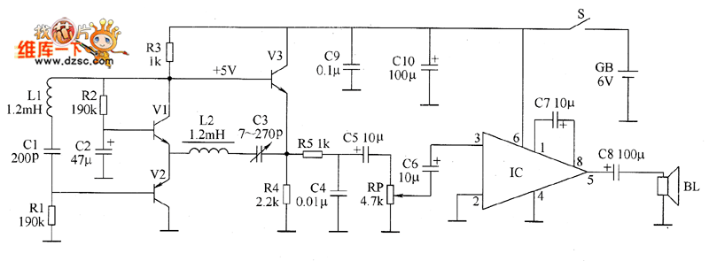
Metal detector circuit diagram 3
The metal detector consists of a probe oscillator, a reference oscillator, an audio amplifier, and various other components, as illustrated in the schematic. The probe oscillator is made up of transistors V1 and V2, a detection coil L1, a capacitor...

oscillator
An oscillator is an electronic circuit that converts energy from a direct-current source into a periodically varying electric output.
An oscillator is a fundamental component in various electronic systems, serving the purpose of generating oscillating signals, typically in the form of...
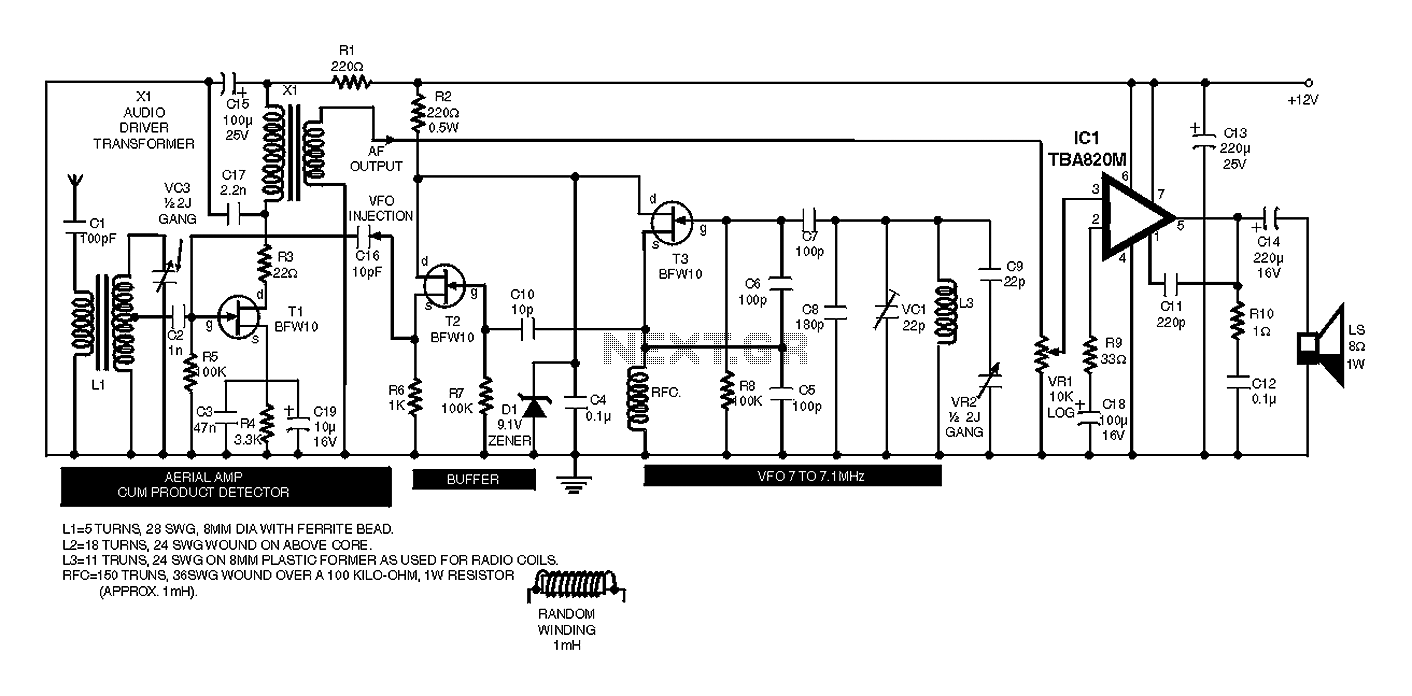
Automatic Dual Output Display
This circuit sequentially lights ten bulbs, first in one direction and then in the opposite direction, creating an appealing visual effect. Gates N1 and N2 form an oscillator, which serves as a clock for the BCD up/down counter CD4510 (IC2)....
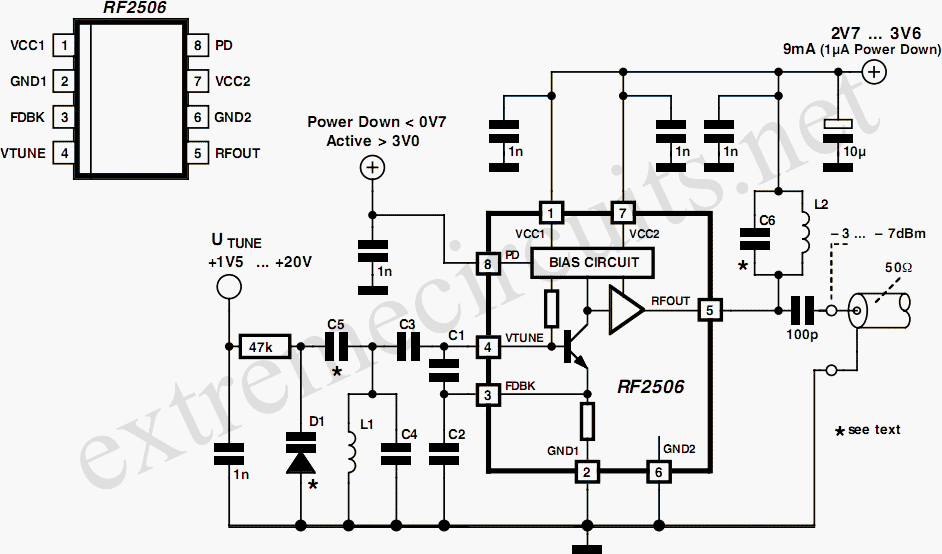
10 to 1000 MHz Oscillator circuit with RF2506
Today, it is no longer necessary to use discrete components for constructing oscillators. Many manufacturers now offer ready-made voltage-controlled oscillator (VCO) integrated circuits (ICs) that require only a few external components to determine the frequency. An example of such an...

Stable Start-Stop Oscillator
Oscillators that generate a predetermined number of pulses are often required in applications such as video work. This oscillator starts 13 ms after the control signal goes high and stops immediately when the input signal goes low.
In electronic applications, pulse...
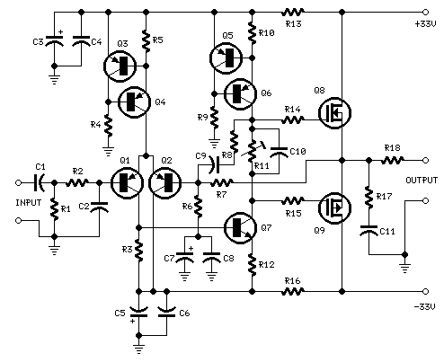
25 Watt MosFet Amplifier
High Quality simple design No need for a preamplifier Can be directly connected to CD players, tuners and tape recorders. Simply add a 10K Log potentiometer (dual gang for stereo) and a switch to cope with the various sources you...