


instrument panel lamp dimmer control
#MC3392
#MC1455
#PWM
#incandescent lamps
#instrument panel
#dimmer control
#low side switch
#automotive lighting
#timing circuit
#pulse width modulation
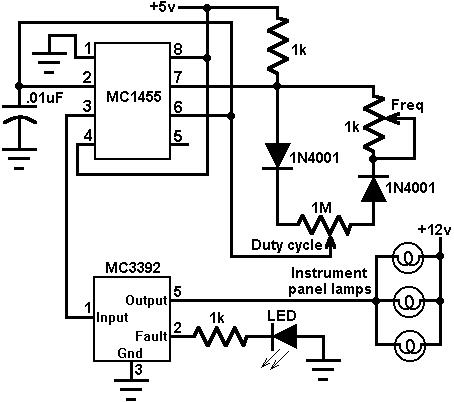
Description: This circuit utilizes an MC3392 low-side protected switch along with an MC1455 timing circuit to create a dimmer control for automotive instrumentation panel lamps. The brightness of incandescent lamps can be adjusted by applying Pulse Width Modulation (PWM) to the input of the MC3392.
The circuit design integrates an MC3392, which functions as a low-side switch, allowing it to control the current flowing to the automotive panel lamps. The MC1455, a timing circuit, is configured to generate a PWM signal that modulates the duty cycle of the output signal. By varying the duty cycle, the average voltage supplied to the lamps is adjusted, thereby controlling their brightness.
The MC3392 is equipped with built-in protection features, ensuring that the circuit can handle load variations and prevent damage to the components. The low-side switching configuration is advantageous in automotive applications as it helps to minimize electromagnetic interference (EMI) and ensures efficient operation.
The MC1455 is typically configured in an astable mode to produce a continuous PWM signal. The frequency and duty cycle of this PWM signal can be adjusted by changing the values of the resistors and capacitors in the timing circuit. This versatility allows for precise control over the lamp brightness, catering to different user preferences and lighting conditions.
In summary, this circuit effectively combines the MC3392 and MC1455 to provide a reliable and adjustable dimming solution for automotive instrumentation panel lamps, enhancing visibility and user experience while maintaining safety and component integrity.This circuit uses an MC3392 low side protected switch and an MC1455 timing circuit to form an automotive instrumentation panel lamp dimmer control. The brightness of incandescent lamps can be varied by Pulse Width Modulating the input of the MC3392..
The circuit design integrates an MC3392, which functions as a low-side switch, allowing it to control the current flowing to the automotive panel lamps. The MC1455, a timing circuit, is configured to generate a PWM signal that modulates the duty cycle of the output signal. By varying the duty cycle, the average voltage supplied to the lamps is adjusted, thereby controlling their brightness.
The MC3392 is equipped with built-in protection features, ensuring that the circuit can handle load variations and prevent damage to the components. The low-side switching configuration is advantageous in automotive applications as it helps to minimize electromagnetic interference (EMI) and ensures efficient operation.
The MC1455 is typically configured in an astable mode to produce a continuous PWM signal. The frequency and duty cycle of this PWM signal can be adjusted by changing the values of the resistors and capacitors in the timing circuit. This versatility allows for precise control over the lamp brightness, catering to different user preferences and lighting conditions.
In summary, this circuit effectively combines the MC3392 and MC1455 to provide a reliable and adjustable dimming solution for automotive instrumentation panel lamps, enhancing visibility and user experience while maintaining safety and component integrity.This circuit uses an MC3392 low side protected switch and an MC1455 timing circuit to form an automotive instrumentation panel lamp dimmer control. The brightness of incandescent lamps can be varied by Pulse Width Modulating the input of the MC3392..
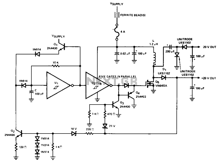
Switching inverter for 12v systems
This PWM control circuit generates control pulses for the DMOS power switch in the flyback circuit. The PWM output produces a pulse width that is proportional to the input control voltage, with the repetition rate governed by an external clock...
250 to 5000 watts PWM DC/AC 220V Power Inverter
The schematic circuit design is for a 250-watt output inverter. To increase the power of the circuit, additional Q7 and Q8 transistors can be added in parallel; each pair contributes an additional 250 watts. For instance, to achieve 750 watts,...
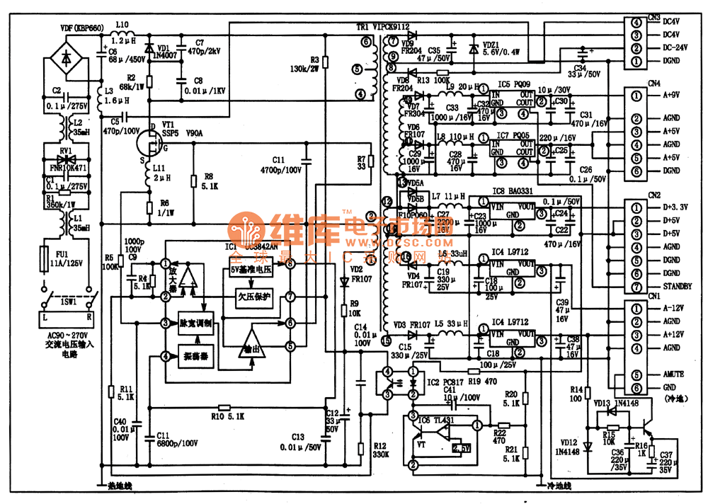
UC3842AN PWM IC diagram
The UC3842AN is a pulse width modulation (PWM) integrated circuit that is commonly utilized in DVD, VCD, and SVCD players, as well as in computers, display systems, and various household appliances' switching power supply circuits.
The UC3842AN is a versatile...
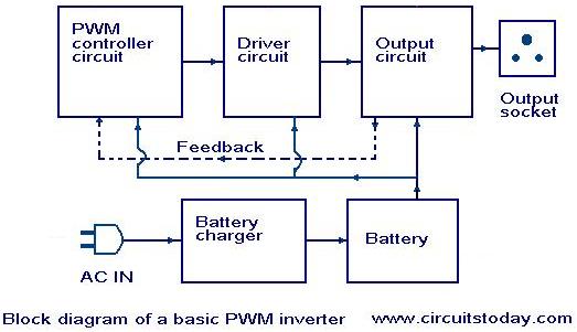
Introduction to PWM Inverters
Nowadays, most inverters available in the market utilize Pulse Width Modulation (PWM) technology. Inverters based on PWM technology exhibit superior performance in several aspects compared to those designed using conventional methods. These PWM inverters typically employ MOSFETs in the output...

Can produce circuits within the range of 1-99% duty cycle of the digital set-precision PWM wave
The circuit described is a crystal oscillation circuit using a CM OS inverting configuration, designed to ensure accurate operation. It employs a BCD counter (IC2) capable of achieving a maximum oscillation frequency of 2 MHz, which is 100 times the...
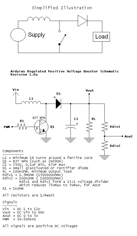
Regulated Positive Voltage Booster
When Q1 is active, a larger current begins to flow through L1 to ground. When Q1 is switched off, the current through L1 tries to remain constant, resulting in an increased voltage. By varying the PWM duty cycle, the current...
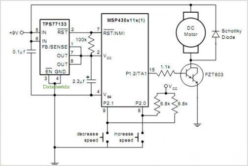
Pwm Dc Motor Control Using Timer A Of The Msp430
The QAMI5516 is an integrated demodulator and decoder solution designed for digital cable receivers, capable of handling compressed video, audio, and data services. This QAM demodulator executes intermediate frequency (IF) to MPEG-2 block processing of QAM carriers. The resulting demodulated...
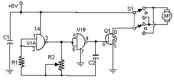
Pulse Width Modulation DC Motor Control
Often, people attempt to control DC motors with a variable resistor or variable resistor connected to a transistor. While the latter approach works well, it generates heat and hence wastes power. This simple pulse width modulation DC motor control eliminates...
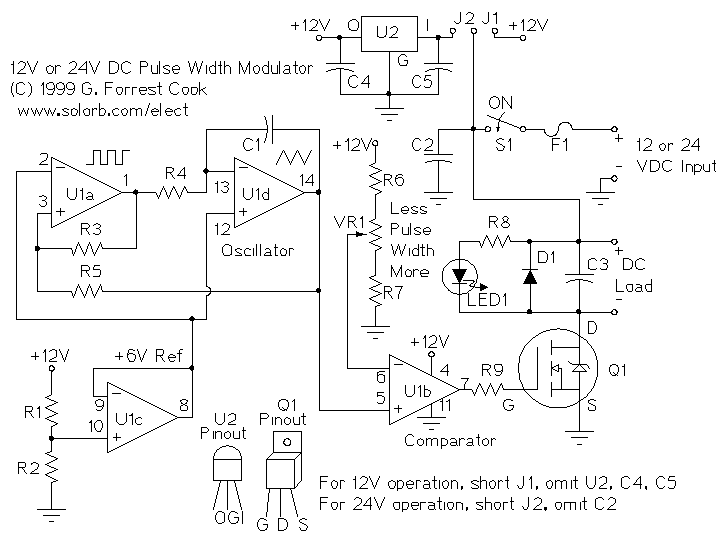
PWM Motor Speed Controller
A pulse width modulator (PWM) is a device that may be used as an efficient light dimmer or DC motor speed controller. The circuit described here is for a general purpose device that can control DC devices which draw up...