


Instrument panel lamp dimmer control Circuit
#MC3392
#MC1455
#PWM
#instrument panel
#lamp dimmer
#incandescent lamps
#low side switch
#timer circuit
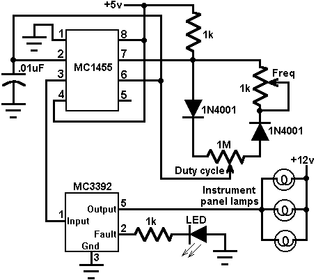
Description: This circuit utilizes an MC3392 low-side protected switch in conjunction with an MC1455 timing circuit to create a dimmer control for automotive instrumentation panel lamps. The brightness of incandescent lamps is adjustable through Pulse Width Modulation (PWM) applied to the MC3392's input. The PWM signal can be sourced directly from the MC1455 timer or a microprocessor. The MC1455 is configured as a free-running clock with adjustable frequency and duty cycle. The typical operating frequency is around 80 Hz when the frequency potentiometer is set to 1.0 kΩ, a value selected to prevent noticeable lamp flicker. The duty cycle can be varied from approximately 3% to 97% using a potentiometer, where 3% results in the lamps being nearly off and 97% results in them being nearly fully on. This circuit can control multiple lamps, provided that the total load current does not exceed 1 amp. An LED indicator is included to signal any system faults, such as overvoltage, current limiting, or thermal shutdown.
The circuit design employs the MC3392 as a low-side switch, which provides a safe method for controlling the power to the lamps. The low-side switching configuration allows for simpler control of the load and helps in managing the heat dissipation effectively. The MC1455 timer serves as the core of the PWM signal generation. By configuring the MC1455 in astable mode, it produces a continuous square wave output, the frequency of which can be adjusted by varying the resistance of the connected potentiometer.
The output frequency of approximately 80 Hz is optimal for automotive applications, as it minimizes the perception of flickering by the human eye, ensuring a smooth and consistent illumination of the panel lamps. The duty cycle adjustment allows for fine-tuning of the lamp brightness, catering to user preferences or specific requirements of the vehicle's instrumentation.
The circuit's design also includes a current limiting feature, ensuring that the total load does not exceed 1 amp, which is crucial for maintaining the integrity of the components and preventing potential damage. The inclusion of an LED indicator enhances the functionality of the circuit by providing visual feedback in the event of a fault condition, allowing for quick diagnosis and troubleshooting. This comprehensive approach to automotive lamp dimming not only enhances user experience but also contributes to the overall safety and reliability of the vehicle's electrical system.This circuit uses an MC3392 low side protected switch and an MC1455 timing circuit to form an automotive instrumentation panel lamp dimmer control. The brightness of incandescent lamps can be varied by Pulse Width Modulating the input of the MC3392.
The modulating signal can be obtained directly from the MC1455 timer (or a microprocessor). The MC1 455 is configured as a free-running clock having a frequency and duty cycle control. The typical timer frequency is approximately 80 Hz when the frequency potentiometer is adjusted to 1. 0k. This frequency was chosen so as to avoid any perceptible lamp flicker. The duty cycle potentiometer controls the duty cycle over a range of about 3% to 97%. When at 3% the lamps are essentialy off, at 97% the lamps are essentially full on. Any number of lamps can be control, so long as the total load current is less than 1 amp. The LED is used to signal the existence of a system fault (overvoltage, current limiting, or thermal shutdown).
The circuit design employs the MC3392 as a low-side switch, which provides a safe method for controlling the power to the lamps. The low-side switching configuration allows for simpler control of the load and helps in managing the heat dissipation effectively. The MC1455 timer serves as the core of the PWM signal generation. By configuring the MC1455 in astable mode, it produces a continuous square wave output, the frequency of which can be adjusted by varying the resistance of the connected potentiometer.
The output frequency of approximately 80 Hz is optimal for automotive applications, as it minimizes the perception of flickering by the human eye, ensuring a smooth and consistent illumination of the panel lamps. The duty cycle adjustment allows for fine-tuning of the lamp brightness, catering to user preferences or specific requirements of the vehicle's instrumentation.
The circuit's design also includes a current limiting feature, ensuring that the total load does not exceed 1 amp, which is crucial for maintaining the integrity of the components and preventing potential damage. The inclusion of an LED indicator enhances the functionality of the circuit by providing visual feedback in the event of a fault condition, allowing for quick diagnosis and troubleshooting. This comprehensive approach to automotive lamp dimming not only enhances user experience but also contributes to the overall safety and reliability of the vehicle's electrical system.This circuit uses an MC3392 low side protected switch and an MC1455 timing circuit to form an automotive instrumentation panel lamp dimmer control. The brightness of incandescent lamps can be varied by Pulse Width Modulating the input of the MC3392.
The modulating signal can be obtained directly from the MC1455 timer (or a microprocessor). The MC1 455 is configured as a free-running clock having a frequency and duty cycle control. The typical timer frequency is approximately 80 Hz when the frequency potentiometer is adjusted to 1. 0k. This frequency was chosen so as to avoid any perceptible lamp flicker. The duty cycle potentiometer controls the duty cycle over a range of about 3% to 97%. When at 3% the lamps are essentialy off, at 97% the lamps are essentially full on. Any number of lamps can be control, so long as the total load current is less than 1 amp. The LED is used to signal the existence of a system fault (overvoltage, current limiting, or thermal shutdown).
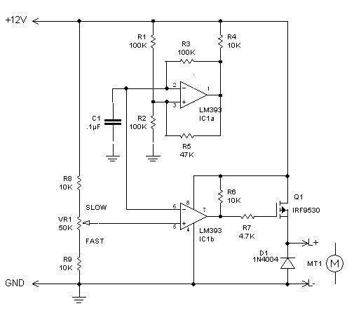
PWM circuit
The inquiry pertains to identifying the component within the circuit that regulates the minimum RPM achievable. The current operational range of the motor is between 1400 and 3700 RPM, and there is an interest in modifying the circuit to lower...
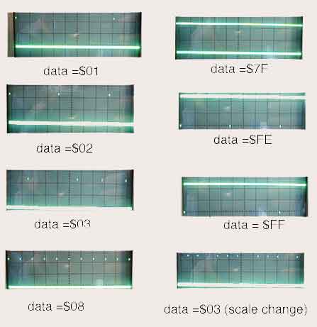
8 Channel PWM with AT90S1200
The assembly code given here was written to see what it would take to make an AT90S1200 generate 8 channels of proper PWM. In this case, by proper, I mean with the maximum high frequency content consistent with the needed...
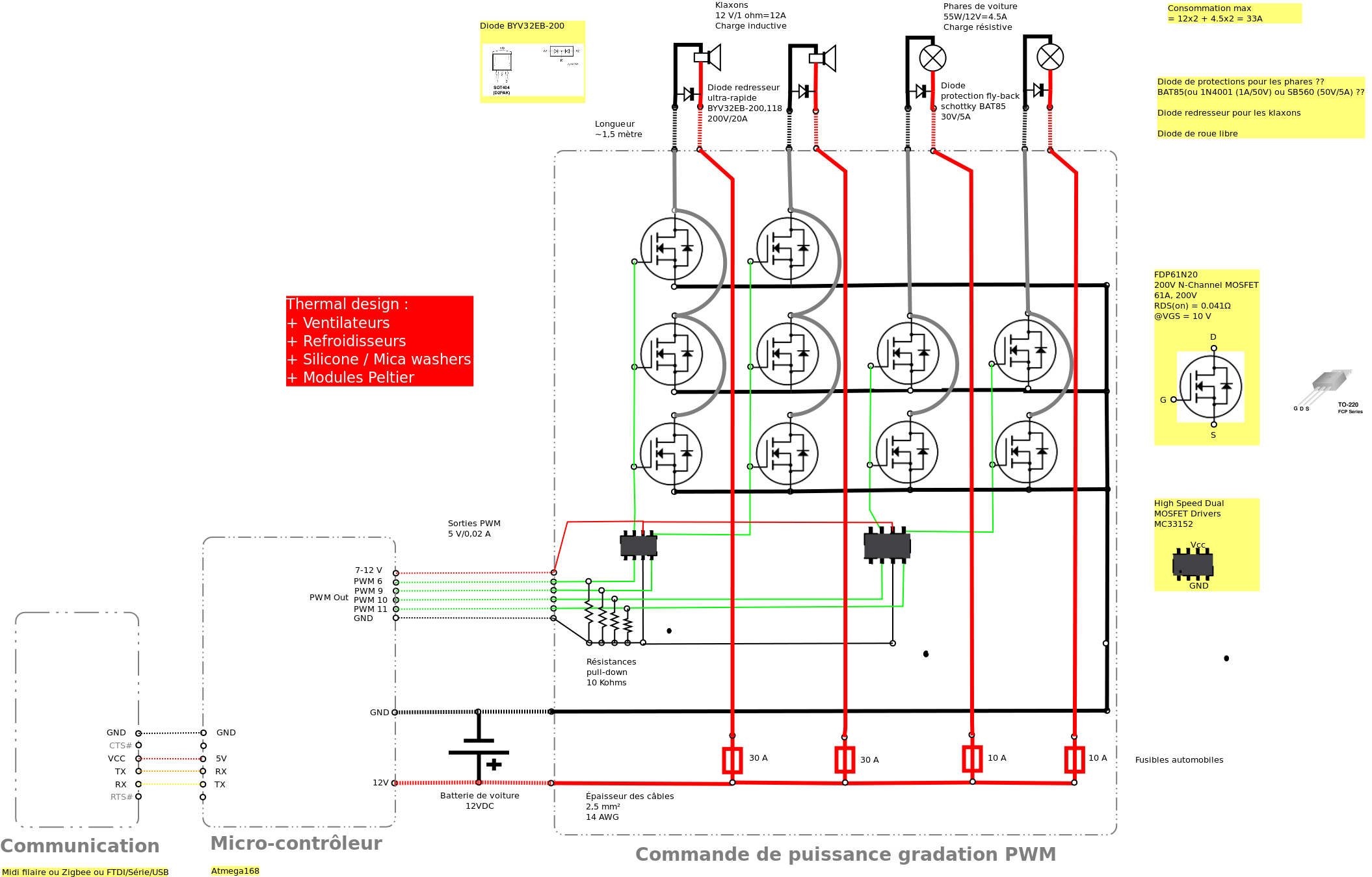
Control car horns in PWM
Past experiences were quite challenging due to the inductive nature of car horns, which require 12A of current, with peak demands reaching 20 to 30A. The current electronic system lacks reliability, given the high intensity. There is a need to...
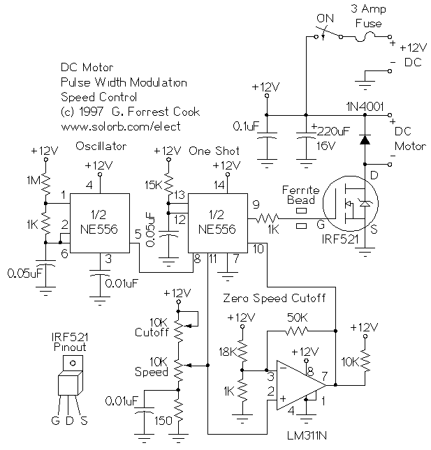
PWM DC Motor Speed Control
This is a circuit for controlling the speed of small DC motors; it works nicely as a speed controller for an HO or N gauge model railroad. More: The left half of the 556 dual timer IC is used as...
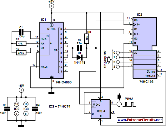
Discrete PWM Generator Circuit
PWM waveforms are frequently employed to regulate the speed of DC motors. The mark/space ratio of the digital waveform can be established either by utilizing an adjustable analog voltage level (as seen in a NE555-based PWM generator) or through digital...
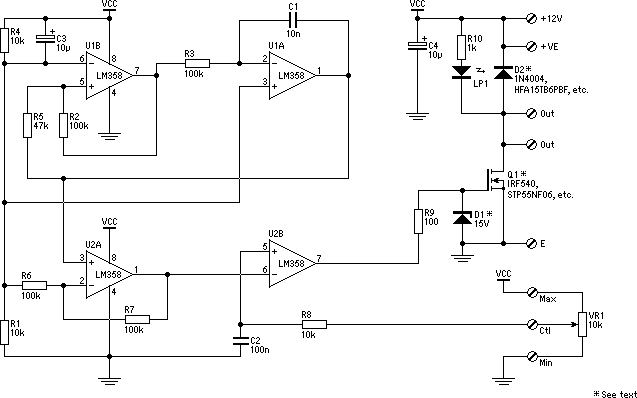
PWM Dimmer/Motor Speed Controller
This project addresses the need for a simple circuit that can dim LED lights or control the speed of 12V DC motors. The circuit utilizes Pulse Width Modulation (PWM) to manage the effective or average current flowing through an LED...
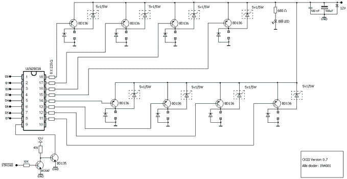
8 Channel software controlled fanbus with PWM
This article was previously published, but the intention is to spread the idea further, potentially inspiring new concepts. An improved version was being developed using an ULN2803A instead of multiple BC547B transistors and optional Zener diodes to ensure that the...
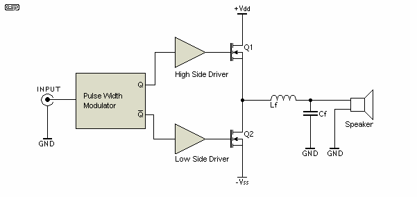
pmw driver circuit class d amp
One of the critical components is a PWM speed controller, allowing for fine speed adjustments instead of just an "on" mode that runs at full power. This is important for safety. A basic stamp microcontroller was purchased, which includes a...
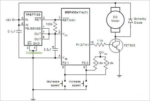
Pwm Dc Motor Control Using Timer A Of The Msp430
The QAMI5516 is an integrated demodulator and decoder solution designed for digital cable receivers, capable of handling compressed video, audio, and data services. This QAM demodulator executes intermediate frequency (IF) to MPEG-2 block processing of QAM carriers. The resulting demodulated...