


Layout Guidelines with Example Layout for the MAX16922 PMIC
#PMIC
#power-management
#layout guidelines
#MAX16922
#automotive electronics
#emissions reduction
#circuit design
#performance optimization
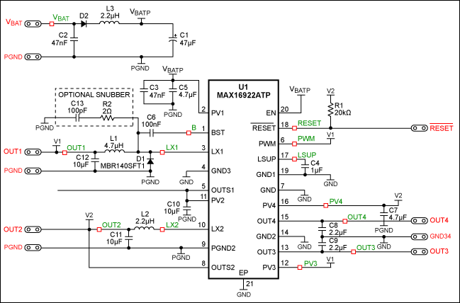
Description: The article explains how to layout a standard MAX16922 automotive PMIC (power-management IC) to maximize performance and minimize emissions.
The MAX16922 is a versatile power management integrated circuit designed specifically for automotive applications. Its layout is crucial for optimizing performance and reducing electromagnetic interference (EMI). A well-designed PCB layout can significantly enhance the efficiency of power distribution and thermal management, which are critical in automotive environments.
When laying out the MAX16922, several key considerations must be taken into account. First, the placement of the IC should be near the power input and output connections to minimize trace lengths, which helps reduce parasitic inductance and resistance. This proximity is essential for maintaining voltage levels and ensuring stable operation under varying load conditions.
Ground planes play a vital role in the layout of the MAX16922. A solid ground plane should be implemented to provide a low-impedance return path for high-frequency currents. This minimizes ground bounce and improves overall circuit stability. Additionally, it is advisable to separate analog and digital grounds to prevent noise coupling, which can adversely affect sensitive analog components.
Decoupling capacitors should be placed as close as possible to the IC's power pins. This arrangement helps to filter out high-frequency noise and provides instantaneous current during transient load changes. The selection of capacitor types and values should be based on the specific application requirements, taking into account factors such as ESR (Equivalent Series Resistance) and ESL (Equivalent Series Inductance).
Thermal management is another critical aspect of the layout. The MAX16922 can generate heat during operation, especially under high load conditions. Adequate copper area should be allocated for heat dissipation, and thermal vias can be employed to connect to inner layers of the PCB for better heat spreading. It is also beneficial to consider the placement of heat-sensitive components away from the IC to prevent thermal interference.
Routing of traces should be done with care to avoid sharp bends and minimize loop areas, which can contribute to EMI. Differential pairs should be routed together to maintain signal integrity, and proper termination techniques should be utilized to further reduce reflections.
In conclusion, a meticulous approach to the layout of the MAX16922 PMIC can lead to improved performance, reduced emissions, and enhanced reliability in automotive applications. Following best practices in PCB design, including careful component placement, effective grounding strategies, and thermal management, will ensure optimal operation of the power management circuit.Article explains how to layout a standard MAX16922 automotive PMIC (power-management IC) to maximize performance and minimize emissions..
The MAX16922 is a versatile power management integrated circuit designed specifically for automotive applications. Its layout is crucial for optimizing performance and reducing electromagnetic interference (EMI). A well-designed PCB layout can significantly enhance the efficiency of power distribution and thermal management, which are critical in automotive environments.
When laying out the MAX16922, several key considerations must be taken into account. First, the placement of the IC should be near the power input and output connections to minimize trace lengths, which helps reduce parasitic inductance and resistance. This proximity is essential for maintaining voltage levels and ensuring stable operation under varying load conditions.
Ground planes play a vital role in the layout of the MAX16922. A solid ground plane should be implemented to provide a low-impedance return path for high-frequency currents. This minimizes ground bounce and improves overall circuit stability. Additionally, it is advisable to separate analog and digital grounds to prevent noise coupling, which can adversely affect sensitive analog components.
Decoupling capacitors should be placed as close as possible to the IC's power pins. This arrangement helps to filter out high-frequency noise and provides instantaneous current during transient load changes. The selection of capacitor types and values should be based on the specific application requirements, taking into account factors such as ESR (Equivalent Series Resistance) and ESL (Equivalent Series Inductance).
Thermal management is another critical aspect of the layout. The MAX16922 can generate heat during operation, especially under high load conditions. Adequate copper area should be allocated for heat dissipation, and thermal vias can be employed to connect to inner layers of the PCB for better heat spreading. It is also beneficial to consider the placement of heat-sensitive components away from the IC to prevent thermal interference.
Routing of traces should be done with care to avoid sharp bends and minimize loop areas, which can contribute to EMI. Differential pairs should be routed together to maintain signal integrity, and proper termination techniques should be utilized to further reduce reflections.
In conclusion, a meticulous approach to the layout of the MAX16922 PMIC can lead to improved performance, reduced emissions, and enhanced reliability in automotive applications. Following best practices in PCB design, including careful component placement, effective grounding strategies, and thermal management, will ensure optimal operation of the power management circuit.Article explains how to layout a standard MAX16922 automotive PMIC (power-management IC) to maximize performance and minimize emissions..
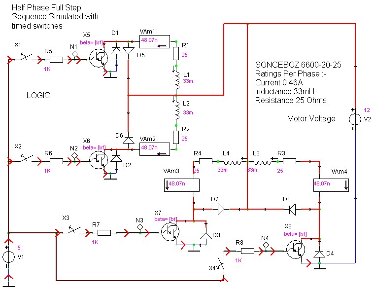
case stepper
Beige Bag Software has been offering affordable and innovative circuit design tools since 1990. B2 Spice provides schematics as well as analog, digital, and mixed-mode electronic circuit simulation. It integrates with EAGLE and CADSTAR PCB software.
B2 Spice is a powerful...
Electronic Projects
This program includes circuit design CAD, simulation, and auto-routing PC layout. PSPICE is also utilized at Unisys, which offers more capabilities but costs six times as much and requires annual renewal. With these requirements and others in mind, a variation...