


Lights-on-reminder
#piezo transducer
#ignition
#car lights
#diode
#current flow
#alert system
#energy saving
#vehicle electronics
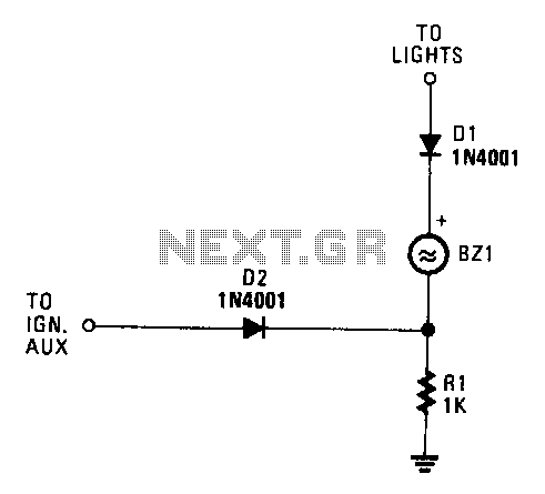
Description: When both the ignition and the car lights are activated, piezo transducer BZ1 does not draw any current and remains silent. If only the ignition is on, diode D1 is reverse-biased, which prevents current from flowing through BZ1. However, when the lights are on and the ignition is off, the transducer is energized and emits a sound to alert the user to turn the lights off. Furthermore, with the ignition off and the lights on, diode D2 is reverse-biased, which stops current from flowing to the ignition. Resistor R1 is employed to prevent a short circuit when the ignition is active.
The circuit described involves a piezo transducer (BZ1) that functions as an alert mechanism in a vehicle lighting system. The operation of BZ1 is contingent upon the states of the ignition and the vehicle lights. When both systems are active, BZ1 remains inactive due to the lack of current flow. The presence of diode D1 plays a crucial role in this scenario by being reverse-biased, which effectively blocks any current from reaching BZ1 when the ignition is on.
In contrast, when the ignition is off while the lights are still on, BZ1 becomes energized. This occurs because the reverse bias on D1 is no longer applicable, allowing current to flow and activate the transducer, thereby producing an audible alert. This feature is essential for preventing battery drain by reminding the driver to turn off the lights.
Additionally, diode D2 serves to prevent any current from flowing to the ignition circuit when the ignition is off and the lights are on, ensuring that the vehicle's ignition system remains unaffected. Resistor R1 is strategically placed in the circuit to provide a safeguard against potential short circuits when the ignition is turned on. This resistor ensures that there is a controlled path for current, thereby protecting sensitive components within the ignition system.
Overall, this circuit design effectively integrates both alerting and protective functions, enhancing the usability and safety of the vehicle's lighting system.With both the ignition and the car lights on, piezo transducer BZl draws no current and remains silent. With only the ignition on, diode Dl is reverse-biased and so prevents current flow through BZL. However, when the lights are on and the ignition is off, the transducer becomes energized and sounds to alert you to tum the lights off.
With the ignition off and the lights on, D2 is reverse-biased, preventing current from flowing to the ignition. Resistor Rl prevents a short circuit when the ignition is on.
The circuit described involves a piezo transducer (BZ1) that functions as an alert mechanism in a vehicle lighting system. The operation of BZ1 is contingent upon the states of the ignition and the vehicle lights. When both systems are active, BZ1 remains inactive due to the lack of current flow. The presence of diode D1 plays a crucial role in this scenario by being reverse-biased, which effectively blocks any current from reaching BZ1 when the ignition is on.
In contrast, when the ignition is off while the lights are still on, BZ1 becomes energized. This occurs because the reverse bias on D1 is no longer applicable, allowing current to flow and activate the transducer, thereby producing an audible alert. This feature is essential for preventing battery drain by reminding the driver to turn off the lights.
Additionally, diode D2 serves to prevent any current from flowing to the ignition circuit when the ignition is off and the lights are on, ensuring that the vehicle's ignition system remains unaffected. Resistor R1 is strategically placed in the circuit to provide a safeguard against potential short circuits when the ignition is turned on. This resistor ensures that there is a controlled path for current, thereby protecting sensitive components within the ignition system.
Overall, this circuit design effectively integrates both alerting and protective functions, enhancing the usability and safety of the vehicle's lighting system.With both the ignition and the car lights on, piezo transducer BZl draws no current and remains silent. With only the ignition on, diode Dl is reverse-biased and so prevents current flow through BZL. However, when the lights are on and the ignition is off, the transducer becomes energized and sounds to alert you to tum the lights off.
With the ignition off and the lights on, D2 is reverse-biased, preventing current from flowing to the ignition. Resistor Rl prevents a short circuit when the ignition is on.
Automatic Mains Disconnect
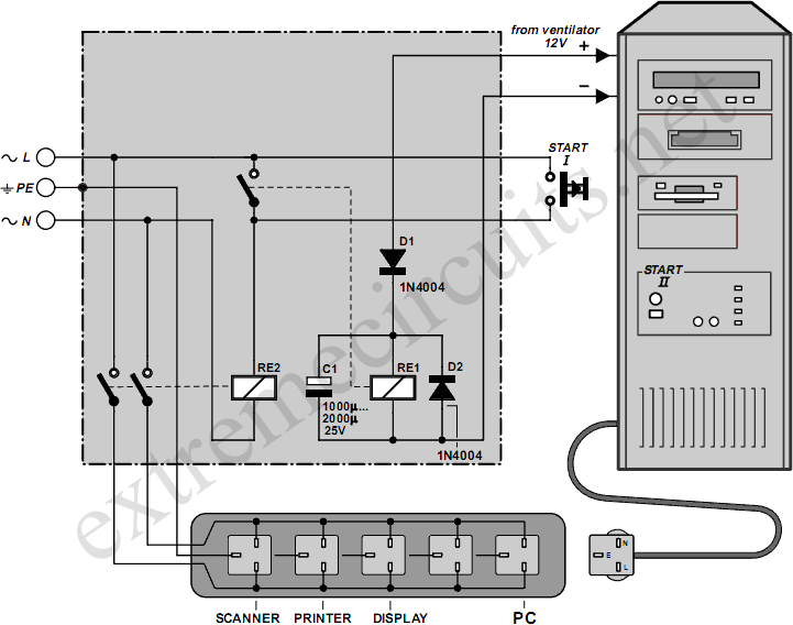
Downloading and CD-burning programs often offer the option to automatically shut down the PC upon completion of their tasks. However, this energy-saving feature is ineffective if all peripheral equipment remains connected to the mains and continues to consume power even...
Diode tester
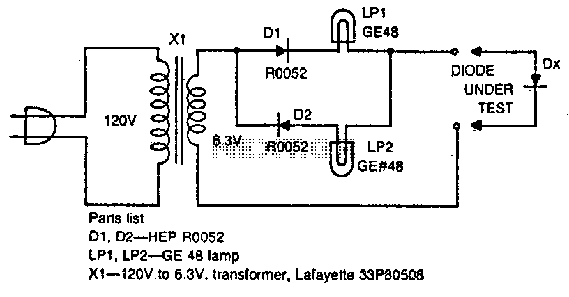
The circuit tests whether a diode is open, shorted, or functioning correctly. If lamp A lights, the diode under test is functional. When lamp B is lit, the diode is good but connected backwards. When both lamps are lit, the...
The electronic energy saving lamp maintenance circuit diagram
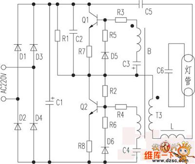
The saving lamp circuit features two main types: glass cover and exposed. The glass cover variants include three series: spherical, cylindrical, and processing types. The first two series consist of four variations: transparent, carved, engraved, and white. These lamps are...
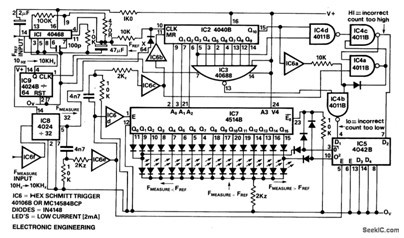
IN4148 Silicon Epitaxial Planar Switching DIODE
This simple diode modulator delivers excellent results when used for high percentage modulation at low signal levels. Constants are shown for a carrier frequency of about 10 MHz, but with a suitable tank, the circuit will yield good results at...
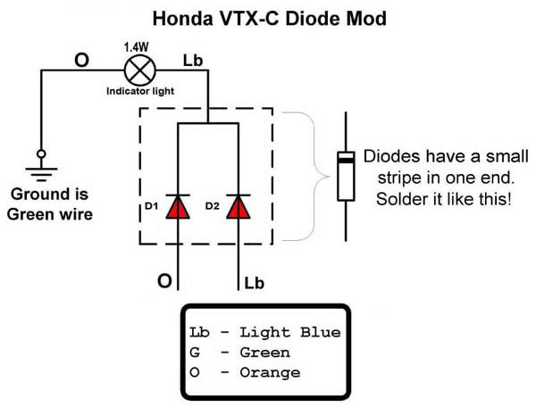
vtx 1800c diode fix
This document provides a guide for creating and installing a diode kit on a Honda VTX 1800C motorcycle. This installation is essential when replacing incandescent turn signals with LED lights.
The installation of a diode kit is a critical step when...
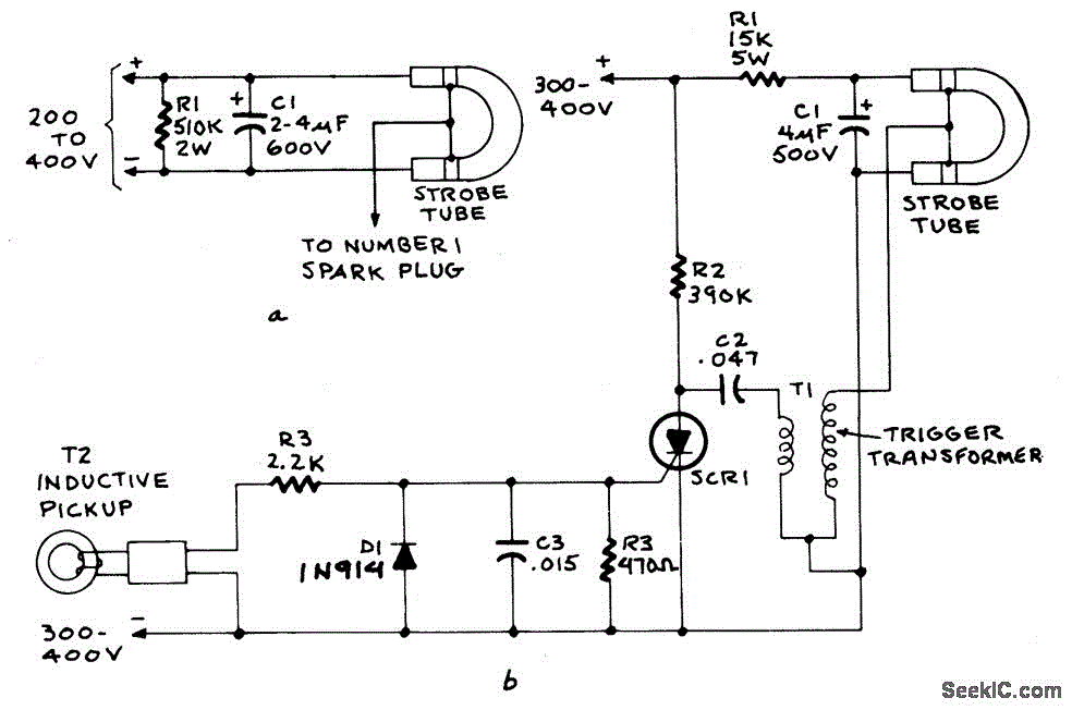
IGNITION TIMING LIGHT
Figure A illustrates the circuit of a direct-trigger timing light. The trigger voltage is obtained from the car's ignition circuit through a direct connection to a spark plug. Figure B depicts a circuit that employs an inductive pickup. A trigger...
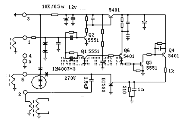
Motorcycle ignition circuit diagram
The anatomy of two ignition experiments revealed a common issue, specifically that both ends of the ignition coil are equipped with a diode. This design choice by manufacturers has implications for performance. The ignition coil generates a negative half-cycle diode...
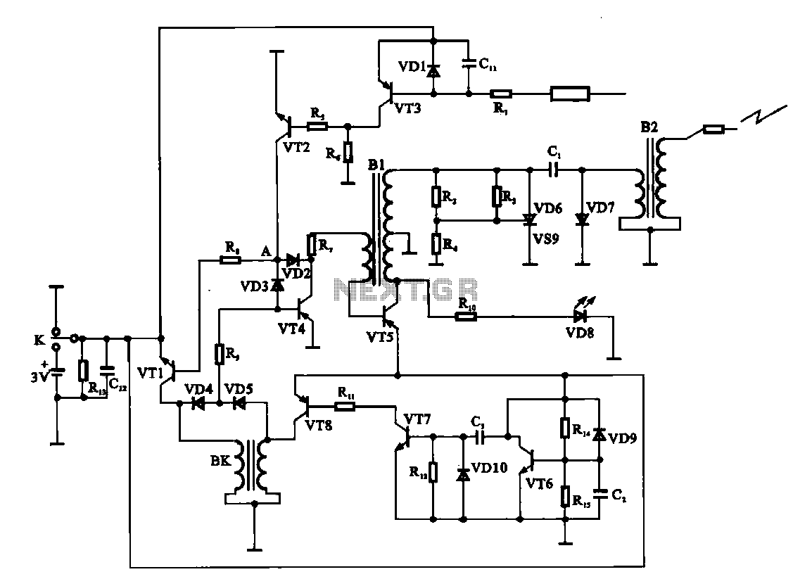
Water heaters electronic ignition circuit
An electronic ignition circuit for a water heater is presented. When the faucet is opened, the switch activates a 3V battery. As capacitor C2 requires time to charge, transistor VT6 remains off. Meanwhile, capacitor C3 charges, allowing transistors VT7 and...
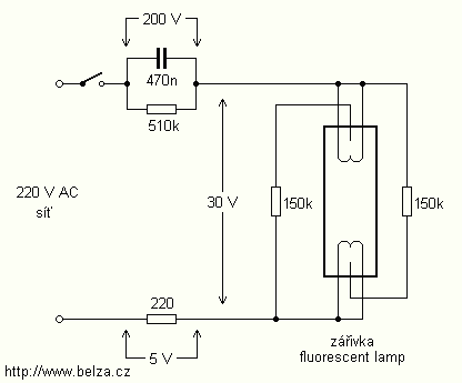
Energy Saving Night Light circuit
The lamps are usually used as ballast or electronic ballast inverter. Here it is used to reduce voltage capacitor reactance. Interesting is also the method of ignition of the auxiliary electrodes involved over 150 Ohm resistors. To start simply involve...