


Lilliput auto video switching for reversing camera
#video switching
#reversing camera
#auto switch
#Lilliput
#car electronics
#video signal
#automotive safety
#dashboard camera
#vehicle accessories
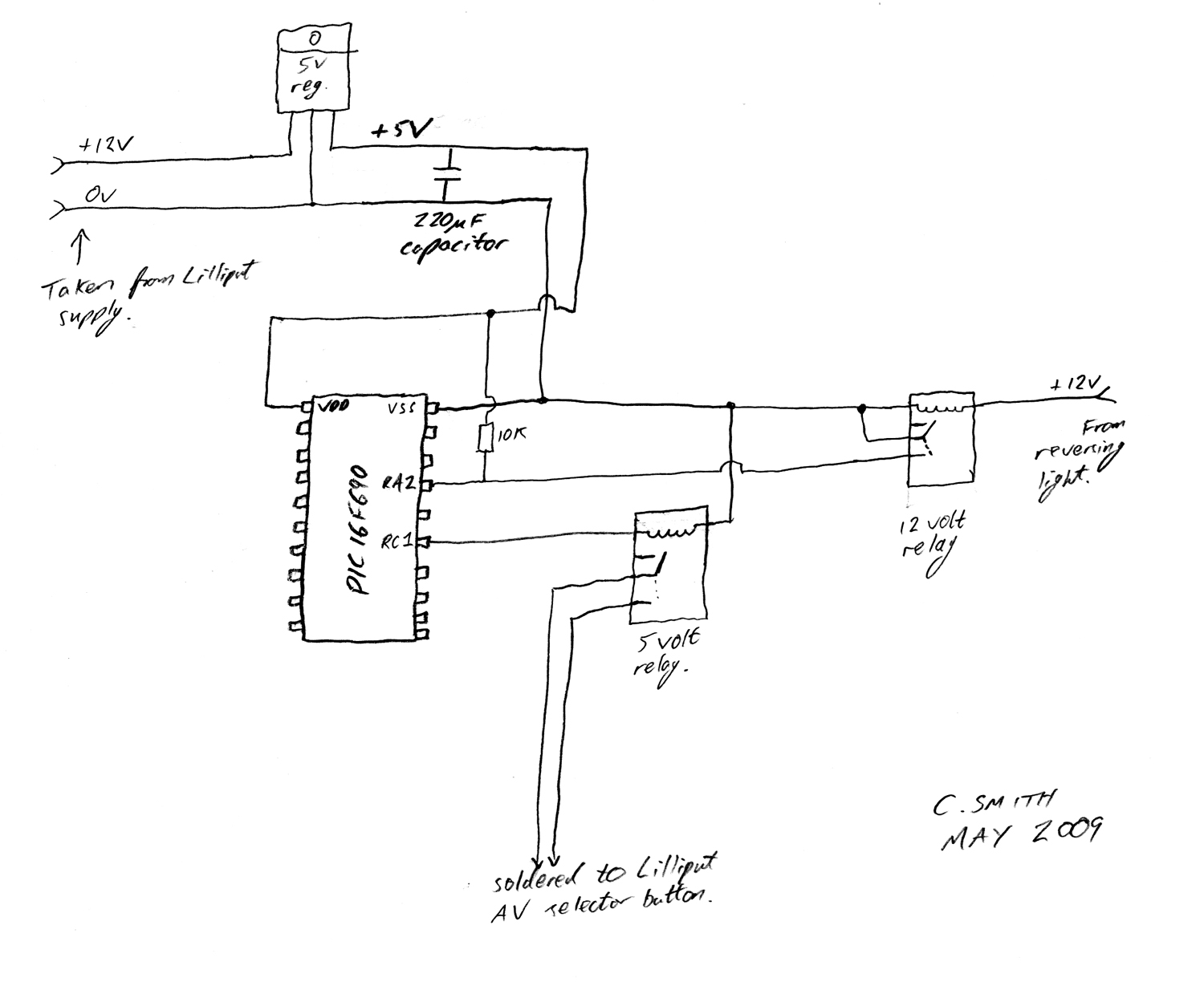
Description: There have been numerous discussions regarding the Lilliput's inability to automatically switch, despite the presence of this feature in the secret menu.
The Lilliput display is a versatile device often used in various applications, including professional video production and monitoring. The issue of automatic switching refers to the display's capability to detect input signals and switch between them without manual intervention. The presence of this feature in the secret menu suggests that it may be a hidden functionality that requires specific conditions or settings to be activated.
To address the automatic switching issue, it is essential to investigate the circuit design of the Lilliput display. The display typically utilizes a microcontroller to manage input signals and control the display output. This microcontroller can be programmed to monitor the input ports for active signals. When a signal is detected, the microcontroller should trigger a switch mechanism that routes the selected input to the display.
A typical schematic for such a system would include the following components:
1. **Microcontroller**: This serves as the central processing unit that interprets input signals and controls the switching mechanism. It is programmed to recognize active signals from various input ports.
2. **Input Ports**: These ports receive signals from different sources such as HDMI, VGA, or composite video. Each port should have signal conditioning circuitry to ensure that the signals are within acceptable voltage levels for processing.
3. **Switching Circuit**: This circuit is responsible for routing the selected input to the display. It may utilize analog switches or relays controlled by the microcontroller. The choice of switching technology can impact the response time and reliability of the switching action.
4. **Power Supply**: A stable power supply is crucial for the microcontroller and other components to function correctly. It should provide the necessary voltage and current levels as specified in the component datasheets.
5. **User Interface**: While the primary focus is on automatic switching, a user interface may be included to allow manual selection and configuration of settings, including enabling or disabling the automatic switching feature.
By ensuring that the microcontroller is properly programmed and that all components are functioning correctly, the automatic switching feature can be effectively utilized, enhancing the overall user experience with the Lilliput display.I have been reading a lot of posts about the Lilliput not being able to `auto switch` even though it is in the secret menu, so I decided to make a..
The Lilliput display is a versatile device often used in various applications, including professional video production and monitoring. The issue of automatic switching refers to the display's capability to detect input signals and switch between them without manual intervention. The presence of this feature in the secret menu suggests that it may be a hidden functionality that requires specific conditions or settings to be activated.
To address the automatic switching issue, it is essential to investigate the circuit design of the Lilliput display. The display typically utilizes a microcontroller to manage input signals and control the display output. This microcontroller can be programmed to monitor the input ports for active signals. When a signal is detected, the microcontroller should trigger a switch mechanism that routes the selected input to the display.
A typical schematic for such a system would include the following components:
1. **Microcontroller**: This serves as the central processing unit that interprets input signals and controls the switching mechanism. It is programmed to recognize active signals from various input ports.
2. **Input Ports**: These ports receive signals from different sources such as HDMI, VGA, or composite video. Each port should have signal conditioning circuitry to ensure that the signals are within acceptable voltage levels for processing.
3. **Switching Circuit**: This circuit is responsible for routing the selected input to the display. It may utilize analog switches or relays controlled by the microcontroller. The choice of switching technology can impact the response time and reliability of the switching action.
4. **Power Supply**: A stable power supply is crucial for the microcontroller and other components to function correctly. It should provide the necessary voltage and current levels as specified in the component datasheets.
5. **User Interface**: While the primary focus is on automatic switching, a user interface may be included to allow manual selection and configuration of settings, including enabling or disabling the automatic switching feature.
By ensuring that the microcontroller is properly programmed and that all components are functioning correctly, the automatic switching feature can be effectively utilized, enhancing the overall user experience with the Lilliput display.I have been reading a lot of posts about the Lilliput not being able to `auto switch` even though it is in the secret menu, so I decided to make a..

TV as display terminal interface circuit diagram
The interface circuit is placed between the computer's standard video signal output terminal and the television. It amplifies the standard 1V (Peak-to-Peak) video signal to 3V (Peak-to-Peak). The negative feedback circuit consists of transistors T1 and T2, providing a wide...
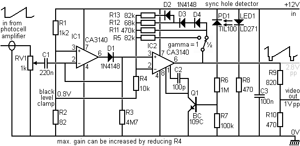
Adding sync pulses to the video signal
This section provides details for generating a composite video output signal from a camera to drive an external monitor. The circuit, designed by Peter Smith, integrates a DC-restorer, a switchable gamma corrector, and a video/sync mixer using a photodiode and...
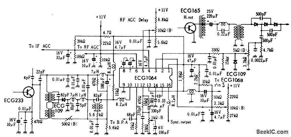
TV_video_signal_processor_circuit_1
TV video signal processor circuit. The ECG1064 chip includes a primary video amplifier, two sync pulse amplifiers, a look-out protector, a noise detector, two noise gates, an automatic gain control (AGC) detector, an intermediate frequency (IF) AGC amplifier, a base...
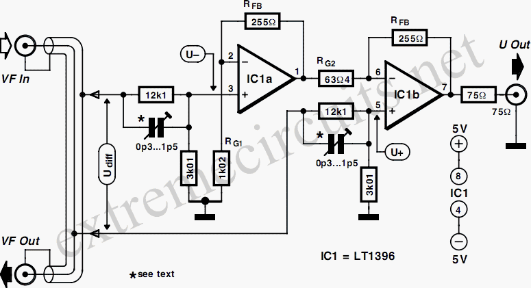
Video-Out Coupling
To connect a video signal to multiple destinations, a distribution amplifier is required to match the 75-ohm video cable. This amplifier terminates the incoming cable at 75 ohms and provides several outputs, each maintaining a 75-ohm output impedance. Typically, this...
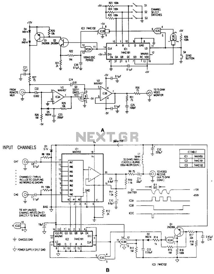
Video Signal Carrier Circuit
In the video system illustrated in Figures A and R, a single coaxial cable transmits power to a remote location, selects one of eight video channels, and returns the selected signal. This system can choose from several remote surveillance camera...
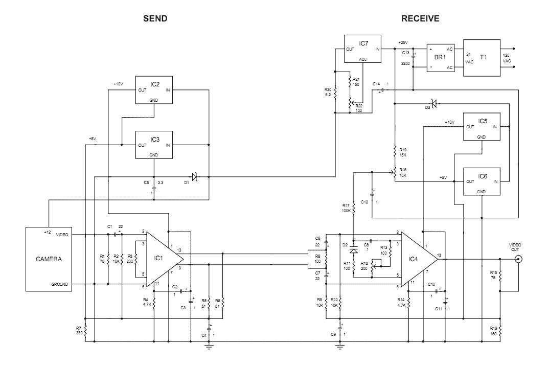
video on telephone line wires
The Videowire converts a baseband video signal into a low impedance differential signal that can be sent over ordinary four conductor telephone wire. A send board mounted close to the camera generates the differential signal and a receive board near...
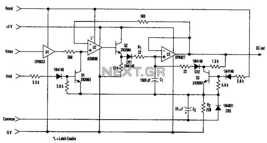
Fast Video Signal Amplitude Measurer Circuit
The amplitude of a video signal can be measured using a straightforward circuit that functions as a modified standard peak detector. This device is capable of verifying RGB signals produced by video RAMDACs. U1 is a high-speed buffer, while U2...
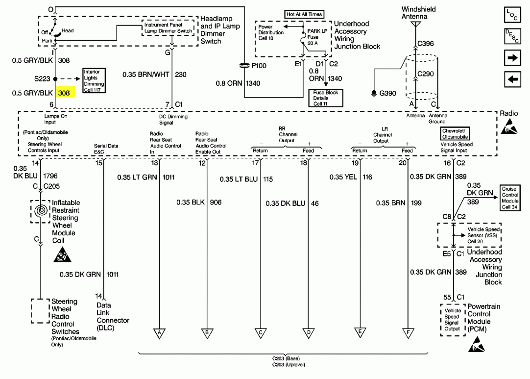
1999 Pontiac Montana: console temperature MPG compass etc. failed
A 1999 Pontiac Montana has an information console that displays temperature, MPG, compass, and other data. This console experienced intermittent failures before completely ceasing to function. Concurrently, the radio display also malfunctioned, though the radio itself remained operational. The display...
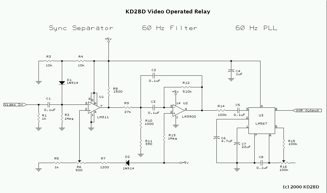
Video Operated Relay
Many Video Operated Relay (VOR) circuits have been published in recent years for use in connection with ATV repeater controllers or automatic videotape logging systems. Unfortunately, many of these circuits fail to properly detect certain video signals depending on their...