


MRC DCC Decoder
#DCC decoder
#G-Scale
#reed switches
#track magnets
#repurposing
#8 amp
#model railroading
#hacking
#function control
#motor control
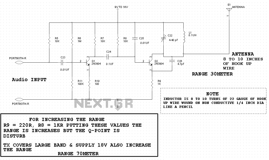
Description: The AD322 is an 8 amp G-Scale DCC decoder. The notes below may be beneficial to owners who wish to understand or repurpose ("hack") the decoder. It has a comprehensive set of functions that could easily be repurposed for various other projects. One modification that comes to mind is to add two reed switches so that magnets on the track can trigger the bell and/or horn. This would be valuable for those who do not have those functions on their DCC Controller. By testing each pin with an oscilloscope, the following information was gathered by cycling through various functions on the board. Note that pin 1 is located in the upper right corner in the photo, next to the small round dimple. Pins are counted 1-10 from right to left for the top row and 11-20 from left to right across the bottom.
The AD322 DCC decoder is designed for G-Scale model trains, facilitating digital control over locomotive functions. It operates at a maximum current of 8 amps, making it suitable for powering larger models. The decoder supports multiple functions, including sound, lighting, and motor control, enabling intricate operation and customization of model trains.
For users interested in enhancing the functionality of the AD322, the addition of reed switches is a practical modification. These switches can be activated by magnets placed on the track, allowing for the triggering of sound functions such as bells or horns without the need for a DCC controller that supports these features. This modification can significantly enhance the realism of train operations, especially in layouts where sound effects are desired but not supported by the existing control system.
The pin configuration of the AD322 is essential for users intending to modify or troubleshoot the decoder. Each pin serves a specific function, and understanding their roles is crucial for effective repurposing. Pin 1, located in the upper right corner, is a reference point for counting the pins. The top row consists of pins 1 through 10, arranged from right to left, while the bottom row contains pins 11 through 20, arranged from left to right. Utilizing an oscilloscope to test each pin can provide insights into the operational status and functionality of the decoder, allowing users to identify which pins correspond to specific functions.
Overall, the AD322 DCC decoder presents a versatile platform for model train enthusiasts looking to customize their layouts, offering opportunities for both functional enhancement and creative modifications.The AD322 is an 8 amp G-Scale DCC decoder. The notes below may be of benefit to owners who wish to understand or repurpose ("hack") the decoder. It has a rather full set of functions that could easily be repurposed for a number of other projects.
One modification that comes to mind is to add two reed switches so that magnets on the track can trigg er the bell and/or horn. This would be valuable for those who don`t have those functions on their DCC Controller. By testing each pin with an oscilloscope I gleaned the following by cycling through various functions on the board. Note that pin 1 is in the upper right corner in the photo - next to the small round dimple. Pins are counted 1-10 from right to left for the top row and 11-20 from left to right across the bottom.
The AD322 DCC decoder is designed for G-Scale model trains, facilitating digital control over locomotive functions. It operates at a maximum current of 8 amps, making it suitable for powering larger models. The decoder supports multiple functions, including sound, lighting, and motor control, enabling intricate operation and customization of model trains.
For users interested in enhancing the functionality of the AD322, the addition of reed switches is a practical modification. These switches can be activated by magnets placed on the track, allowing for the triggering of sound functions such as bells or horns without the need for a DCC controller that supports these features. This modification can significantly enhance the realism of train operations, especially in layouts where sound effects are desired but not supported by the existing control system.
The pin configuration of the AD322 is essential for users intending to modify or troubleshoot the decoder. Each pin serves a specific function, and understanding their roles is crucial for effective repurposing. Pin 1, located in the upper right corner, is a reference point for counting the pins. The top row consists of pins 1 through 10, arranged from right to left, while the bottom row contains pins 11 through 20, arranged from left to right. Utilizing an oscilloscope to test each pin can provide insights into the operational status and functionality of the decoder, allowing users to identify which pins correspond to specific functions.
Overall, the AD322 DCC decoder presents a versatile platform for model train enthusiasts looking to customize their layouts, offering opportunities for both functional enhancement and creative modifications.The AD322 is an 8 amp G-Scale DCC decoder. The notes below may be of benefit to owners who wish to understand or repurpose ("hack") the decoder. It has a rather full set of functions that could easily be repurposed for a number of other projects.
One modification that comes to mind is to add two reed switches so that magnets on the track can trigg er the bell and/or horn. This would be valuable for those who don`t have those functions on their DCC Controller. By testing each pin with an oscilloscope I gleaned the following by cycling through various functions on the board. Note that pin 1 is in the upper right corner in the photo - next to the small round dimple. Pins are counted 1-10 from right to left for the top row and 11-20 from left to right across the bottom.
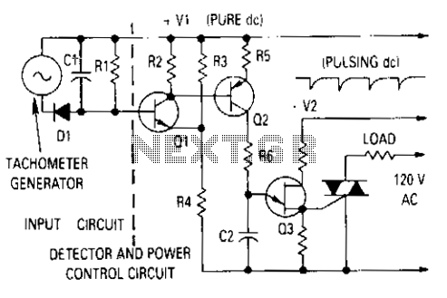
Motor control with tachometer
The generator output is rectified, filtered, and applied between the positive supply voltage and the base of the detector transistor. This configuration provides a negative voltage that reduces the base voltage as the speed increases. During normal operation, if the...
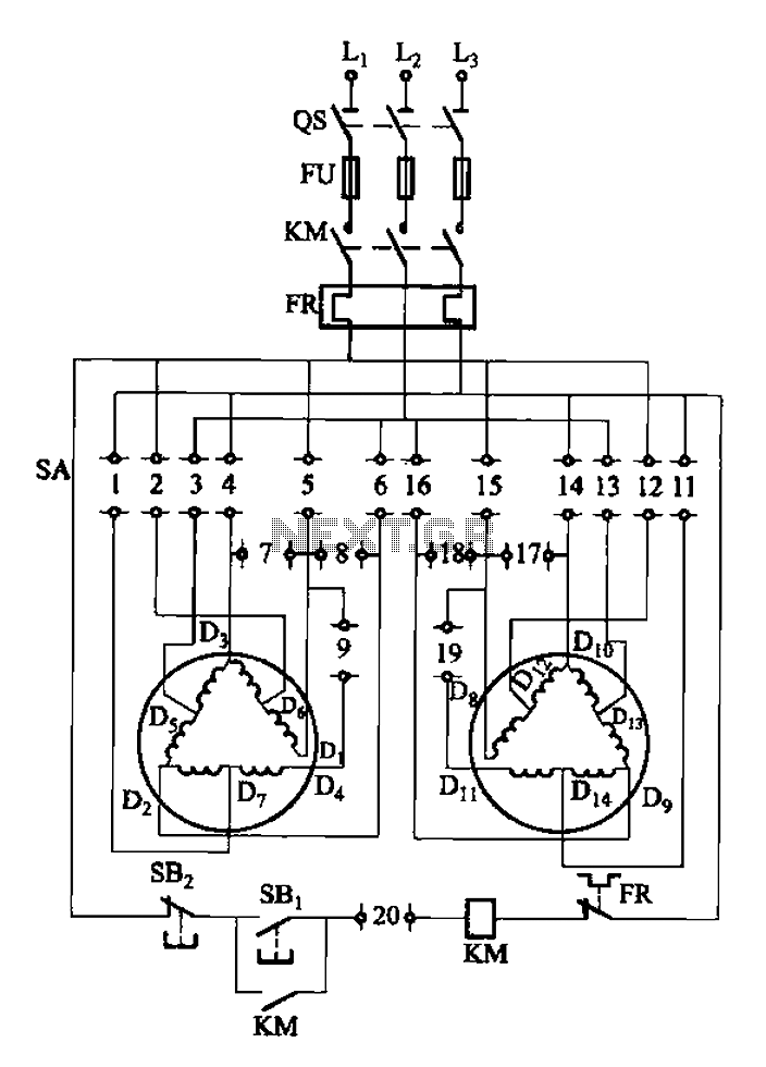
2Y-Y-2 - connection four-speed motor switch control circuit
The 3-119 circuit shown in the figure combines switch SA to realize the stator windings, specifically the 2, Y, and 2Y connections, which correspond to the motor speed n1.
The 3-119 circuit is designed to facilitate the control of motor speed...
Gray Projects
After learning to operate the device, it became evident that inertia posed a significant challenge. The constructed system is notably heavy, making it difficult to initiate motor operation at full speed. Despite having some understanding of physics, practical experience is...
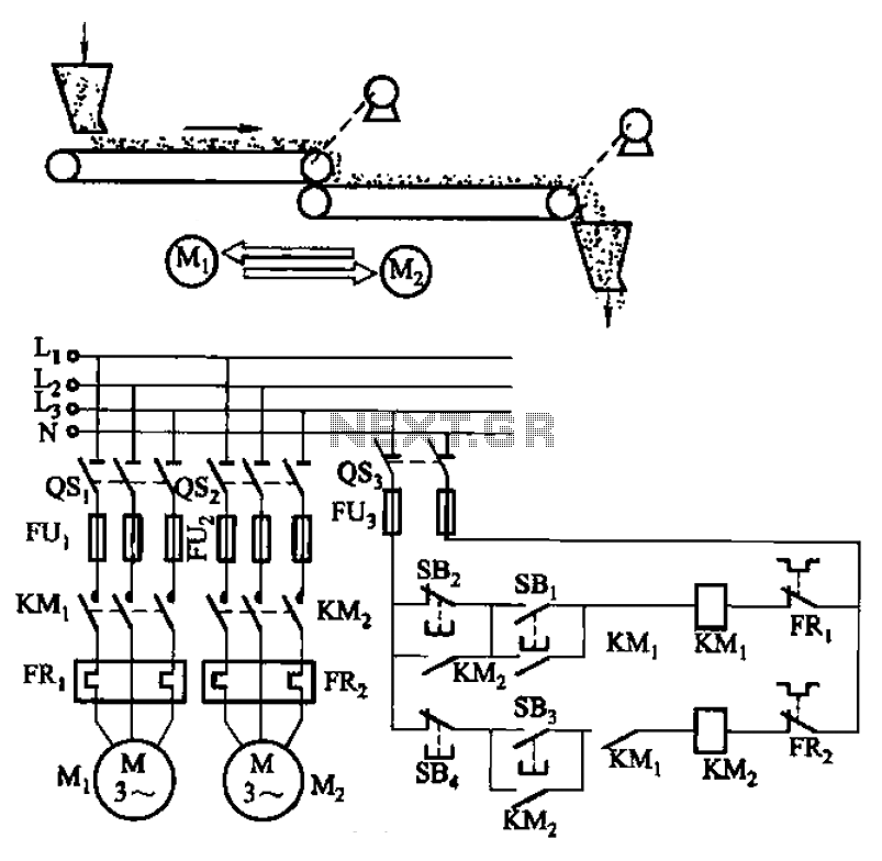
Belt conveyor interlock motor operation sequence control circuit
The circuit depicted in Figure 3-86 utilizes a line utilization time relay to control two motors, starting one before the other after an initial stall. The time relay KTi can be adjusted to modify the starting interval of the two...
motor timer
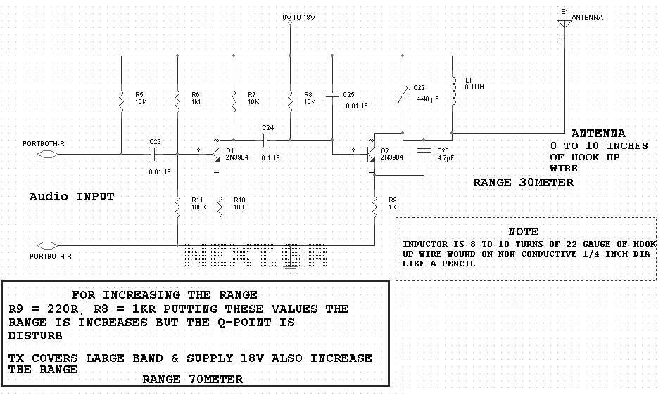
The primary concept is to rotate the motor slightly every 15 seconds. A monofilament line conveys the motion to the ornament, which is wound by the motor and gradually unwinds as the ornament turns. The charging circuit includes a 1...
Direction and speed control
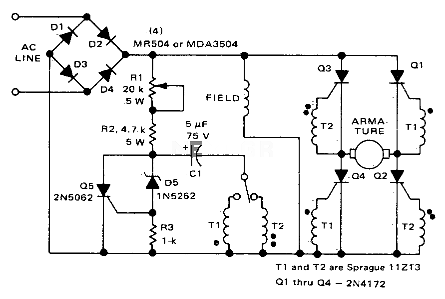
This circuit functions similarly to the one depicted in Fig. 57-4. The key differences include the placement of the field across the rectified supply and the armature being positioned within the SCR bridge. Therefore, the field current is unidirectional while...
2 -Y- connection automatic three-speed motor acceleration control circuit
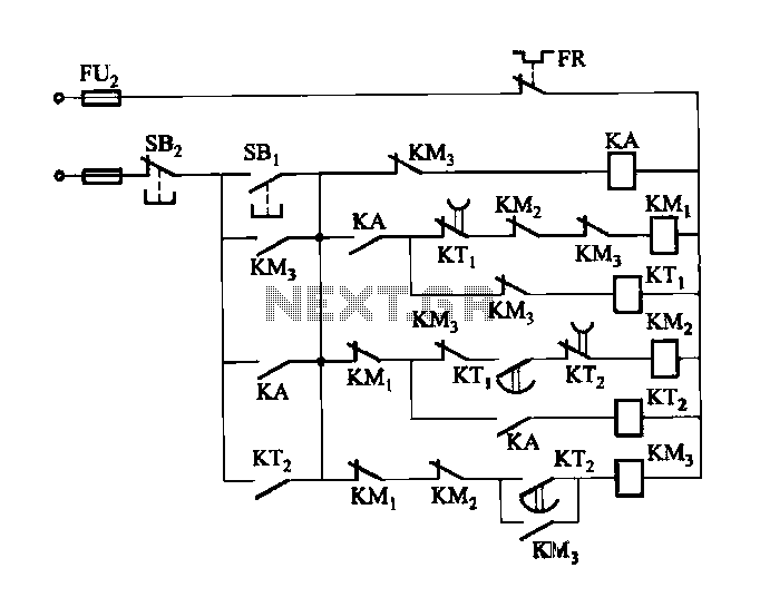
Figure 3-118 illustrates an automatic acceleration control circuit. This circuit employs a male contactor time relay, enabling the motor to start automatically at a low speed before transitioning to high-speed operation.
The automatic acceleration control circuit depicted in Figure 3-118 is...
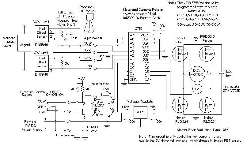
Motorized Video Camera Mount
The camera rotator circuit utilizes a 2716 EPROM to store a logic value table that governs the motor driver (H-bridge) circuit. The schematic illustrates the EPROM data. By employing the EPROM, a significant number of discrete gates are eliminated. The...
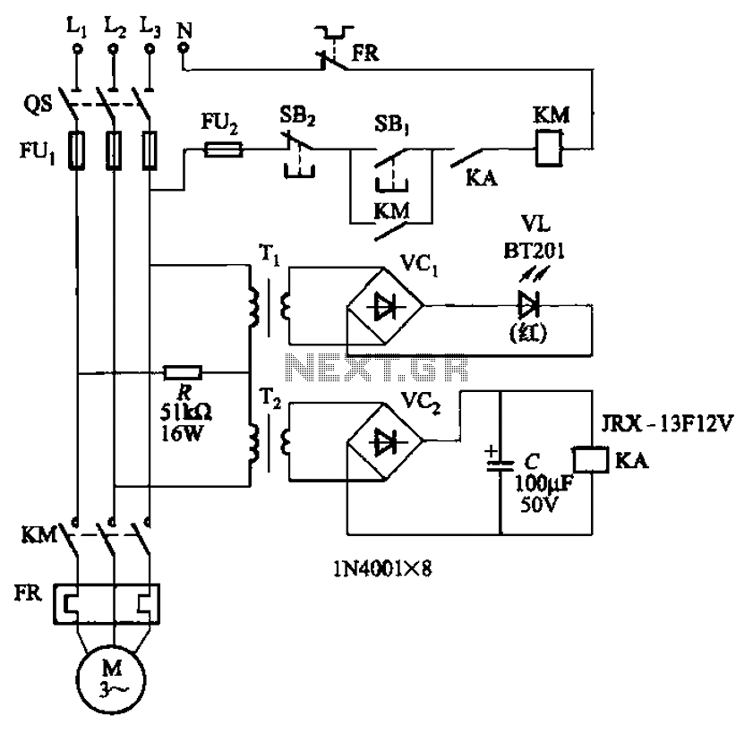
Allowing only one-way operation of the motor-controlled circuit 2
The circuit depicted in Figure 3-92 employs a dual-phase sequence protection relay for sensing. When the power supply exhibits a positive phase sequence (U, V, W), the relay KA is activated. If the power supply maintains the correct phase sequence,...