


pcb Need help with identifying diodes in a 1970s automotive circuit
#diodes
#reverse engineering
#ignition module
#Mercedes-Benz
#PCB
#1970s
#transistors
#resistors
#capacitors
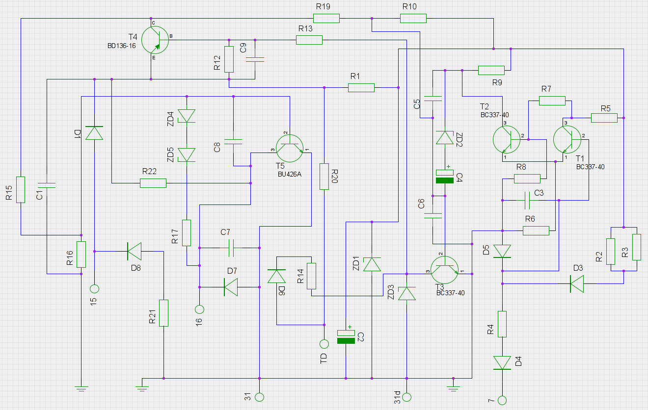
Description: An old ignition module from a 1978 W116 model Mercedes-Benz is being reverse-engineered. The original circuit diagram is not available, so a new one has been created based on the printed circuit board (PCB). The circuit has been assessed to be electrically correct despite its appearance. All resistors, capacitors, and transistors have been identified except for one. The diodes present significant challenges, particularly ZD4, ZD5, D1 to D8, which remain unidentified. ZD4 and ZD5 are not shorted, indicating they are likely rated above 30V, as testing with a 30V power supply has yielded no results. Diodes D3, D5, and D6 are damaged, while D4 is located next to resistor R4. The leftmost black diodes are D1 and D8, both marked "703," and the one beneath them is D7, marked "1849" and "714." The missing T5 transistor is a TO3 packaged power transistor, marked "1120008" and "7/32," with a BU426A suggested as a direct replacement. Transistors T1 to T3 are BCY58IX, and T4 is a BSV15-16K.
The ignition module circuit from the 1978 W116 Mercedes-Benz serves as a crucial component in the vehicle's ignition system, responsible for controlling the timing and delivery of electrical pulses to the ignition coil. The reverse engineering process involves meticulous analysis of the PCB layout, component placement, and interconnections to reconstruct the original circuit functionality.
The identified components include various resistors, capacitors, and transistors, each playing a specific role in the operation of the ignition module. The transistors, specifically the BCY58IX series, act as switches that regulate current flow through the ignition coil, while the BSV15-16K transistor is likely used for voltage regulation or as a driver for higher currents.
The challenge lies primarily with the diodes, particularly ZD4 and ZD5, which are suspected to have high voltage ratings. These diodes may serve as voltage clamping devices or protection components within the circuit. The failure of diodes D3, D5, and D6 indicates potential over-voltage or reverse polarity conditions that could have led to their damage, suggesting that careful consideration should be given to the voltage levels applied during testing.
The identification of the missing T5 transistor, marked "1120008" and "7/32," is critical, as it likely influences the overall performance and reliability of the ignition module. The suggested BU426A replacement indicates compatibility, but verification of electrical characteristics such as current handling and switching speed is essential before substitution.
Overall, this reverse engineering effort aims to restore functionality to the ignition module by accurately mapping out the circuit and identifying suitable replacement components. The detailed understanding of the component functions and their interrelations will aid in troubleshooting and enhancing the performance of the ignition system in the vintage Mercedes-Benz vehicle.An old ignition module from a 1978 W116 model Mercedes-Benz, and I`m trying to "reverse engineer" it. The original circuit diagram is not available to mere mortals, so I have made one based on the PCB itself.
I believe it is, beside being ugly, electrically correct. Thus far I have identified all resistors, caps and transistors (bar one). What I have a huge problem with are the diodes, and any help would be appreciated. ZD4, ZD5, D1 to D8 are unknown. ZD4/ZD5 are not shorted, but I`m getting nowhere with these with my 30V power supply, so they`re probably rated above >30V. D3, D5 and D6 are fried. D4 is just beside R4. The two left-most black diodes are D1 and D8 (both marked "703"), the one underneath them is D7 (marked "1849" and "714").
The missing T5 transistor is a TO3 packaged power transistor marked "1120008" and "7/32". I haven`t cracked this one myself, but have been told a BU426A is a direct replacement for it. T1 to T3 are BCY58IX, T4 is a BSV15-16K.
The ignition module circuit from the 1978 W116 Mercedes-Benz serves as a crucial component in the vehicle's ignition system, responsible for controlling the timing and delivery of electrical pulses to the ignition coil. The reverse engineering process involves meticulous analysis of the PCB layout, component placement, and interconnections to reconstruct the original circuit functionality.
The identified components include various resistors, capacitors, and transistors, each playing a specific role in the operation of the ignition module. The transistors, specifically the BCY58IX series, act as switches that regulate current flow through the ignition coil, while the BSV15-16K transistor is likely used for voltage regulation or as a driver for higher currents.
The challenge lies primarily with the diodes, particularly ZD4 and ZD5, which are suspected to have high voltage ratings. These diodes may serve as voltage clamping devices or protection components within the circuit. The failure of diodes D3, D5, and D6 indicates potential over-voltage or reverse polarity conditions that could have led to their damage, suggesting that careful consideration should be given to the voltage levels applied during testing.
The identification of the missing T5 transistor, marked "1120008" and "7/32," is critical, as it likely influences the overall performance and reliability of the ignition module. The suggested BU426A replacement indicates compatibility, but verification of electrical characteristics such as current handling and switching speed is essential before substitution.
Overall, this reverse engineering effort aims to restore functionality to the ignition module by accurately mapping out the circuit and identifying suitable replacement components. The detailed understanding of the component functions and their interrelations will aid in troubleshooting and enhancing the performance of the ignition system in the vintage Mercedes-Benz vehicle.An old ignition module from a 1978 W116 model Mercedes-Benz, and I`m trying to "reverse engineer" it. The original circuit diagram is not available to mere mortals, so I have made one based on the PCB itself.
I believe it is, beside being ugly, electrically correct. Thus far I have identified all resistors, caps and transistors (bar one). What I have a huge problem with are the diodes, and any help would be appreciated. ZD4, ZD5, D1 to D8 are unknown. ZD4/ZD5 are not shorted, but I`m getting nowhere with these with my 30V power supply, so they`re probably rated above >30V. D3, D5 and D6 are fried. D4 is just beside R4. The two left-most black diodes are D1 and D8 (both marked "703"), the one underneath them is D7 (marked "1849" and "714").
The missing T5 transistor is a TO3 packaged power transistor marked "1120008" and "7/32". I haven`t cracked this one myself, but have been told a BU426A is a direct replacement for it. T1 to T3 are BCY58IX, T4 is a BSV15-16K.

ALTIUM DESIGNER
The PCB is at the center of any electronic product. Literally, the enclosure surrounds the board, and figuratively, all the mathematics, the science, the software, these all run on the board. That’s why the PCB is at the center of...
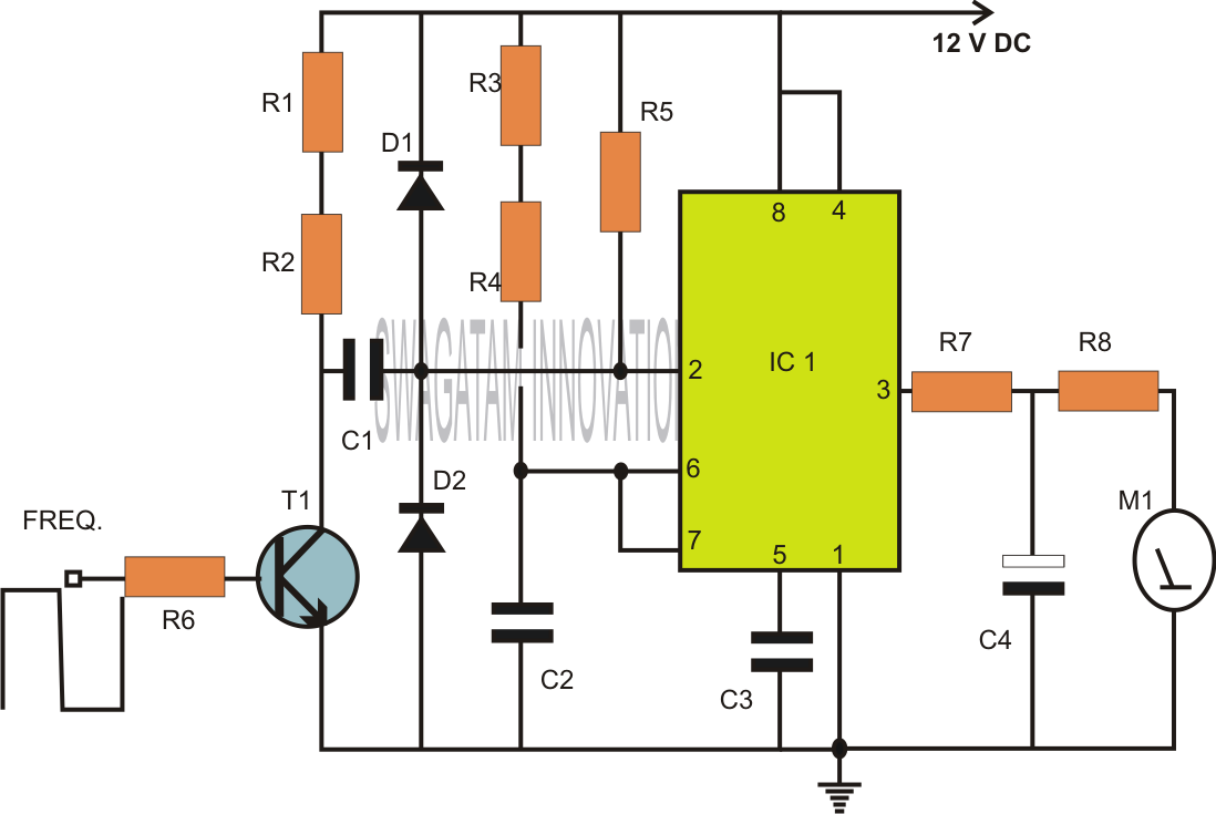
how to build inexpensive frequency
Capacitors are major electronic components classified as passive components. They are extensively used in electronic circuits, and virtually no circuit can be constructed without these essential parts. The primary function of a capacitor is to block direct current (DC) while...

Free-PCB
FreePCB is a free, open-source printed circuit board layout editor for Microsoft Windows, released under the GNU General Public License. It was designed to be easy to learn and easy to use, yet capable of professional-quality work. More: It does...
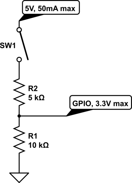
resistors Current flows from the source towards the sink
The circuit is designed to limit the maximum voltage between the GPIO input pin and the current source to 3.3V. This is achieved through a voltage divider configuration where the voltage across the 10K resistor is 3.3V, while the voltage...
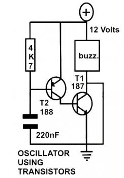
basic oscillator circuit using two
This schematic diagram represents a basic oscillator circuit utilizing two transistors. When the transistors and several passive components are connected as illustrated, the circuit begins to oscillate. The oscillation frequency can be modified by altering the values of either the...
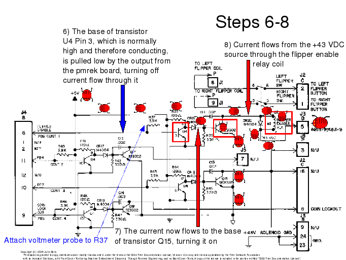
Reverse Engineering
Reverse engineering is employed for educational purposes and to counteract the inclination to overlook the tangible aspects of machinery. This approach emphasizes the importance of engaging with the physical objects themselves rather than relying exclusively on symbolic representations of information.
Reverse...
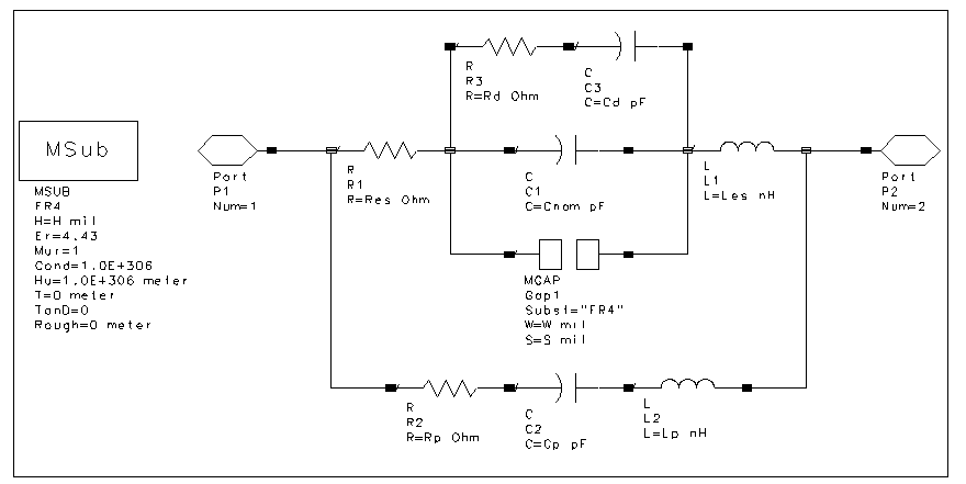
muRata Manufacturing Measurement-Based SMT Capacitors
The schematic design of the equivalent circuit model for Murata Manufacturing's measurement-based GRH series SMT capacitors is derived from device measurements and modeling conducted by Murata. This model is applicable to capacitors mounted on an FR4 substrate, with constant substrate...
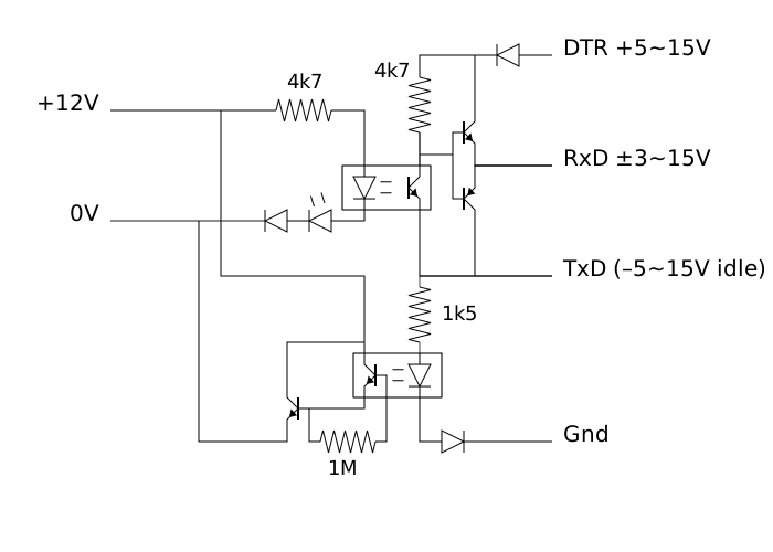
Reverse engineering the Elco heating protocol
The initial step involves searching online for information. After some investigation, it was discovered that the QAA75 sensor is manufactured by Siemens. This expanded the search parameters. It was found that Siemens refers to the communication method as a "Boiler...
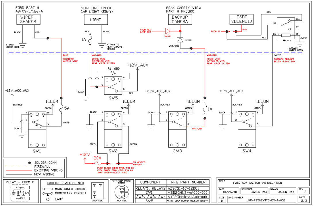
Uplifter Switches
A +12V switched wire was routed back to the camera wiring and connected at the same point as the reverse lights. This configuration allows either the reverse lights or the switch to activate the camera. The critical component in this...