


RPM switch for 6th ports or VDI
#rpm switch
#solenoid control
#rev-limiter
#adjustable
#automotive electronics
#shift light
#VDI
#rotary engine
#Rob Weinstock
#fc3s.org
Warning: Undefined array key "extension" in /var/www/html/nextgr/view-circuit.php on line 445
Deprecated: strtolower(): Passing null to parameter #1 ($string) of type string is deprecated in /var/www/html/nextgr/view-circuit.php on line 445

Description: A circuit diagram for an adjustable RPM switch can be utilized to activate solenoids for auxiliary ports, VDI, shift lights, or other applications. This circuit is adapted from a rev-limiter circuit designed for rotary engines. Special acknowledgment is given to Rob Weinstock from the fc3s.org list for his assistance in refining it.
Two of these switches were constructed and installed in June during a VDI swap, and they have been functioning effectively since then. The cost of parts per switch is approximately $10 CAD. It is important to note that the installed switches were mounted away from heat sources to prevent potential adverse effects on the components. Additionally, LED indicators for power and the "switched on" state were incorporated, although these are not depicted in the circuit layout.
While reviewing the S5 FSM, it was observed that the auxiliary ports and VDI only function under load conditions. In this case, a GXL model equipped with auto-adjusting suspension features a switch on the accelerator pedal that sends a 12V signal to the AAS computer when the throttle exceeds half. To simulate the "under load" effect, the 12V power for the RPM switches was derived from this switch, ensuring that they operate only when full throttle is applied. This approach may be worth considering for those undertaking a VDI swap or converting auxiliary ports to electronic activation.
The adjustable RPM switch circuit typically consists of a microcontroller or timer IC that monitors the engine RPM, a potentiometer for setting the desired RPM threshold, and output control circuitry to activate the solenoids. The microcontroller receives input from the RPM sensor and compares it against the user-defined threshold set by the potentiometer. When the RPM exceeds the threshold, the microcontroller sends a signal to the output stage, which can drive the solenoid or other connected devices.
In addition to the core components, the circuit may include protective features such as flyback diodes across the solenoid coils to prevent voltage spikes when the solenoids are deactivated. Proper grounding and power supply decoupling are essential to ensure stable operation and minimize noise in the circuit. The use of LED indicators provides visual feedback, enhancing user experience and facilitating troubleshooting.
Overall, this adjustable RPM switch circuit represents a versatile solution for various automotive applications, particularly in enhancing the functionality of auxiliary systems. Its simple design, low cost, and adaptability make it an appealing option for automotive enthusiasts looking to implement electronic control in their vehicles.A circuit diagram for an adjustable rpm switch. It ’s something you can use to activate solenoids for auxiliary ports, VDI, shift light, or anything else you can think of. The circuit is adapted from a rev-limiter circuit for rotaries. In particular, I ’d like to thank Rob Weinstock from the fc3s. org list for his help tweaking it. I built and installed two of these switches in June when I did a VDI swap, and so far they ’ve been working fine. Parts cost per switch is only about $10 CAD! Note my installed photo, I ’ve mounted them away from heat, as I don ’t know how that might affect the components.
Also, not shown in the circuit layout, I added LED indicators for power, and the ‘switched on ’ state. One other note – I had been looking at the S5 FSM, and noted that the aux. ports and VDI only operate under load. I have a GXL, which came with auto-adjusting suspension. Part of that system is a switch on the accelerator pedal, which sends a 12V signal to the AAS computer above about half throttle.
To approximate the ‘under load ’ effect, I took the 12V power for the rpm switches from this switch, so they only operate when I ‘floor it ’. Just something you might want to try if you ’re doing the VDI swap or changing your aux. ports to electronic activation.
Two of these switches were constructed and installed in June during a VDI swap, and they have been functioning effectively since then. The cost of parts per switch is approximately $10 CAD. It is important to note that the installed switches were mounted away from heat sources to prevent potential adverse effects on the components. Additionally, LED indicators for power and the "switched on" state were incorporated, although these are not depicted in the circuit layout.
While reviewing the S5 FSM, it was observed that the auxiliary ports and VDI only function under load conditions. In this case, a GXL model equipped with auto-adjusting suspension features a switch on the accelerator pedal that sends a 12V signal to the AAS computer when the throttle exceeds half. To simulate the "under load" effect, the 12V power for the RPM switches was derived from this switch, ensuring that they operate only when full throttle is applied. This approach may be worth considering for those undertaking a VDI swap or converting auxiliary ports to electronic activation.
The adjustable RPM switch circuit typically consists of a microcontroller or timer IC that monitors the engine RPM, a potentiometer for setting the desired RPM threshold, and output control circuitry to activate the solenoids. The microcontroller receives input from the RPM sensor and compares it against the user-defined threshold set by the potentiometer. When the RPM exceeds the threshold, the microcontroller sends a signal to the output stage, which can drive the solenoid or other connected devices.
In addition to the core components, the circuit may include protective features such as flyback diodes across the solenoid coils to prevent voltage spikes when the solenoids are deactivated. Proper grounding and power supply decoupling are essential to ensure stable operation and minimize noise in the circuit. The use of LED indicators provides visual feedback, enhancing user experience and facilitating troubleshooting.
Overall, this adjustable RPM switch circuit represents a versatile solution for various automotive applications, particularly in enhancing the functionality of auxiliary systems. Its simple design, low cost, and adaptability make it an appealing option for automotive enthusiasts looking to implement electronic control in their vehicles.A circuit diagram for an adjustable rpm switch. It ’s something you can use to activate solenoids for auxiliary ports, VDI, shift light, or anything else you can think of. The circuit is adapted from a rev-limiter circuit for rotaries. In particular, I ’d like to thank Rob Weinstock from the fc3s. org list for his help tweaking it. I built and installed two of these switches in June when I did a VDI swap, and so far they ’ve been working fine. Parts cost per switch is only about $10 CAD! Note my installed photo, I ’ve mounted them away from heat, as I don ’t know how that might affect the components.
Also, not shown in the circuit layout, I added LED indicators for power, and the ‘switched on ’ state. One other note – I had been looking at the S5 FSM, and noted that the aux. ports and VDI only operate under load. I have a GXL, which came with auto-adjusting suspension. Part of that system is a switch on the accelerator pedal, which sends a 12V signal to the AAS computer above about half throttle.
To approximate the ‘under load ’ effect, I took the 12V power for the rpm switches from this switch, so they only operate when I ‘floor it ’. Just something you might want to try if you ’re doing the VDI swap or changing your aux. ports to electronic activation.
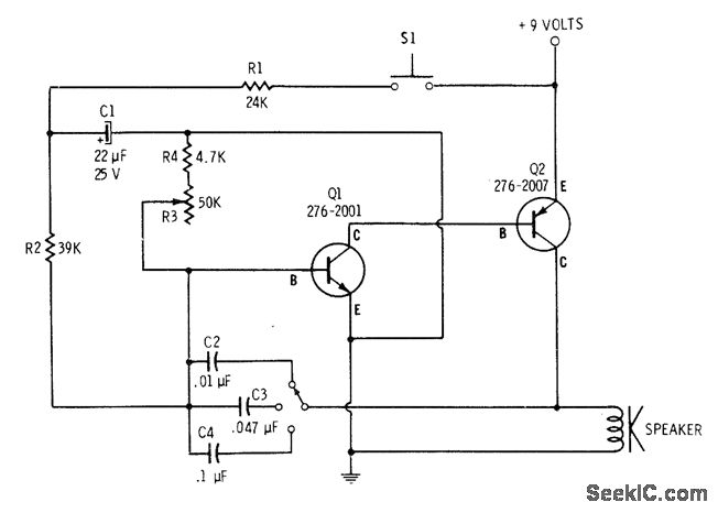
ADJUSTABLE SIREN
The tone is adjustable through a multiposition switch that changes capacitors in the oscillator circuit. The speed, or rate of frequency change, of the siren is controlled with resistor R3. A 4700-ohm resistor is placed in series with R3 to...
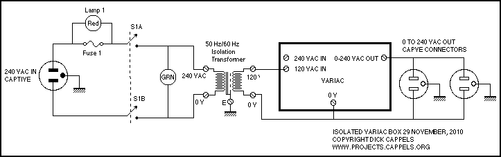
Adjustable Auto transformer
An isolation transformer and a variable auto transformer, very much like a Variac. Fuse 1 protects against gross overload. Lamp 1, across the Fuse 1, is a red incandescent pilot lamp and it lights up in the event of a...
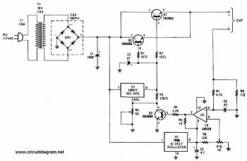
Adjustable Regulated Battery Charger circuit diagram
This battery charger circuit is regulated and adjustable, enabling it to charge most NiCAD batteries. It can accommodate both single cells and multiple battery cells connected in series or parallel. The maximum voltage of the batteries should not exceed 18V....
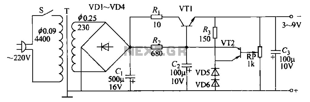
Adjustable from 3 to 9V 100mA power supply circuit
A 3-9V adjustable 100mA power supply is presented, featuring a series regulator circuit that utilizes amplifier tubes. The output voltage can be continuously adjusted between 3V and 9V, with a maximum output current of 100mA, making it suitable for powering...
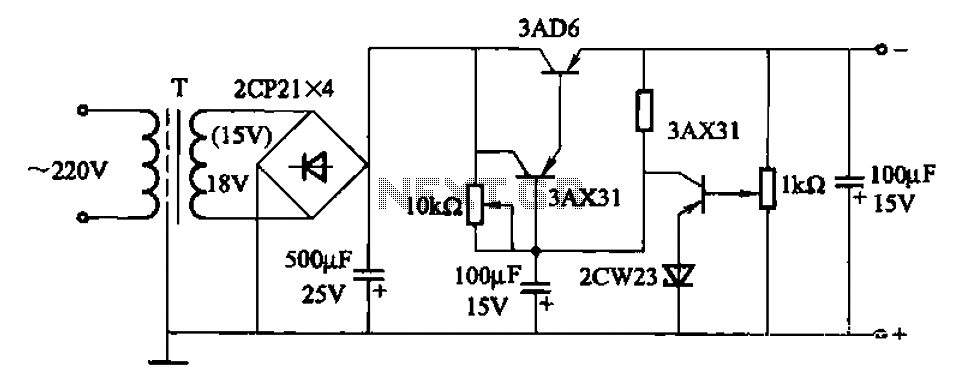
6 to 15V 500mA adjustable power supply circuit
A power supply circuit designed to operate within a voltage range of 6 to 15V, providing a current output of 500mA. This circuit includes an adjustable amplification segment and utilizes a composite transistor configuration for its power supply.
The described power...
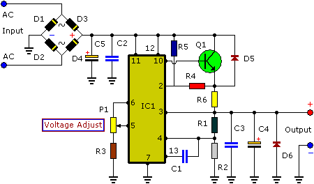
3-30V 3A Adjustable Regulated DC Power Supply
This power supply is designed as either an auxiliary or a permanent power supply for various common circuits that require a stabilized DC voltage ranging from 3 to 30V, provided that the current consumption does not exceed 3A. Additionally, this...

Configurable Power Supply Circuit
The adjustable power supply can be reconfigured by changing the value of V2 and enhancing other components as needed. The output voltage is calculated using the formula Vnm = 1.25 (1 + R2/R^). Additionally, R2 can be modified as required.
The...
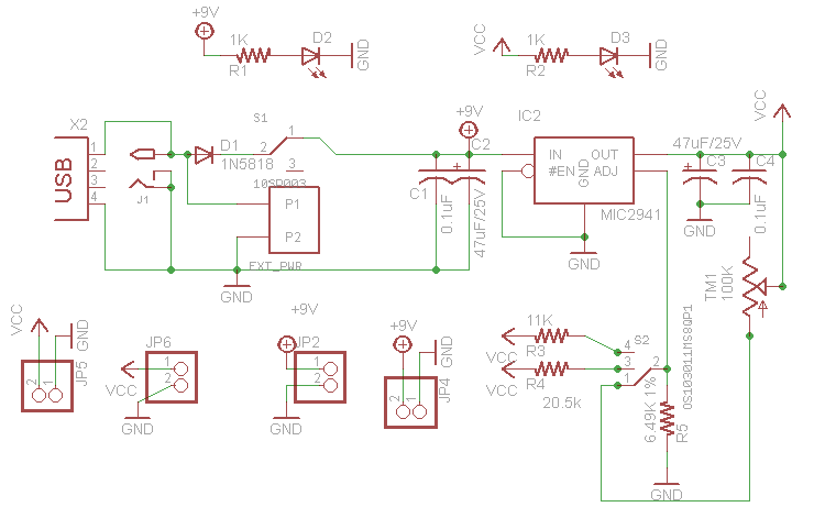
Very Low Dropout Adjustable Breadboard Power Supply
This project outlines the design of a very low dropout adjustable power supply. A reliable power supply is crucial for electronic projects. Although numerous existing designs for adjustable power supplies are available, this particular design introduces enhancements that increase its...
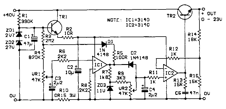
Adjustable Power Supply
A variable power supply is required for repairs on CB and audio equipment, featuring excellent current limiting and protection. The designed circuit delivers a current from zero to approximately 4.25A at a voltage range of zero to about 23V. The...