


running lights brake light to work but not the turn signal harness
#brake light
#turn signal
#wiring harness
#automotive lighting
#electrical troubleshooting
#vehicle electronics
#car repair
#LED lights
#circuit diagnosis
#automotive electrical
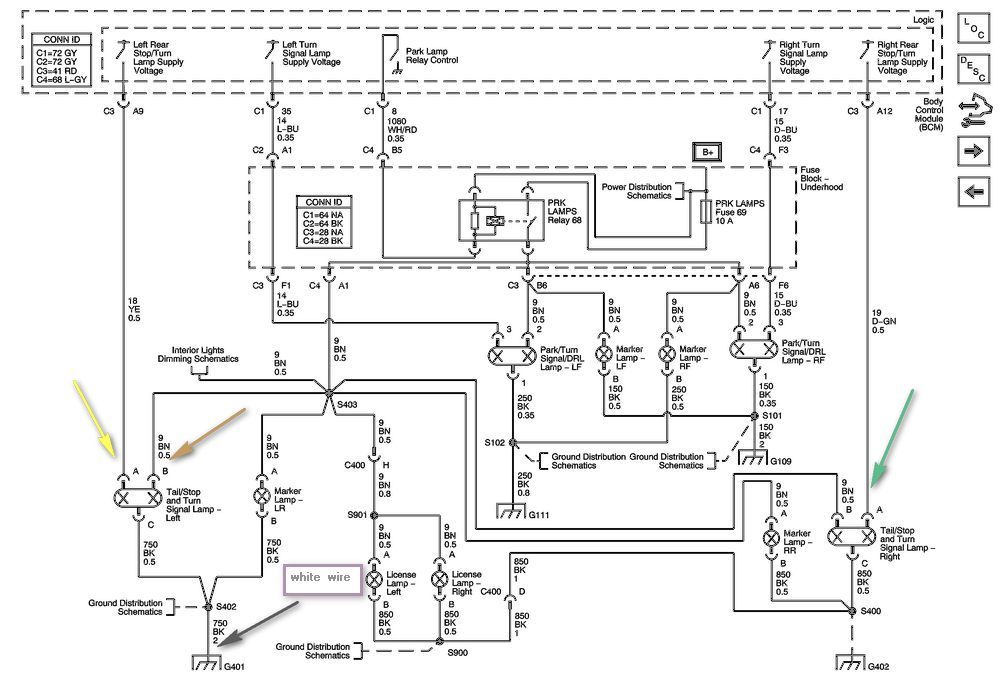
Description: The left side of the vehicle operates correctly, with the running lights and brake light functioning properly. However, the turn signal is not working when wired directly into the harness. There is a preference to avoid purchasing a plug-in harness due to the urgency of the situation.
The circuit in question involves the left side lighting system of a vehicle, specifically focusing on the integration of the turn signal with the existing wiring harness. The left side is confirmed to have operational running lights and brake lights, indicating that the power supply and ground connections are intact for these functions. The issue arises with the turn signal, which suggests a potential fault in the wiring or the turn signal relay.
To troubleshoot this circuit, it is essential to verify the following components:
1. **Wiring Connections**: Check the integrity of the connections within the harness. Look for any signs of fraying, corrosion, or disconnections that may impede the flow of current to the turn signal.
2. **Turn Signal Relay**: Inspect the turn signal relay for proper operation. A malfunctioning relay can prevent the turn signal from activating even if the wiring is intact. Testing the relay with a multimeter can determine if it is functioning correctly.
3. **Grounding**: Ensure that the turn signal has a proper ground connection. A poor ground can lead to erratic behavior or complete failure of the turn signal.
4. **Switch Functionality**: The turn signal switch on the steering column should also be examined. If the switch is faulty, it may not send the appropriate signal to the relay, resulting in a non-functional turn signal.
5. **Fuses**: Check the fuse associated with the turn signal circuit. A blown fuse can interrupt the circuit and prevent the turn signal from operating.
By systematically checking these components, one can identify the root cause of the turn signal malfunction without needing to resort to purchasing a new plug-in harness. A detailed wiring diagram specific to the vehicle model can further aid in pinpointing the exact wiring paths and connections involved in the turn signal system.the left side works fine and i`ve got the left side running lights and brake light to work but not the turn signal I am wiring it right into the harness` and do not want to have to buy the plug in harnes as i need it done asap Ask-a-doc Web sites: If you`ve got a quick question, you can try to get an answer from sites that say they have various sp ecialists on hand to give quick answers. Justanswer. com. Traffic on JustAnswer rose 14 percent. and had nearly 400, 000 page views in 30 days. inquiries related to stress, high blood pressure, drinking and heart pain jumped 33 percent. I was having a terrible problem with the wheel bearings on my 98 Chevy Cavalier and I suspect that using this website saved me plenty of time and money. Todd L Rochester NY I was having a terrible problem with the wheel bearings on my 98 Chevy Cavalier and I suspect that using this website saved me plenty of time and money.
Todd L Rochester NY Wonderful service, prompt, efficient, and accurate. Couldn`t have asked for more. I cannot thank you enough for your help. Mary C. Freshfield, Liverpool, UK This expert is wonderful. They truly know what they are talking about, and they actually care about you. They really helped put my nerves at ease. Thank you so much! Alex Los Angeles, CA Thank you for all your help. It is nice to know that this service is here for people like myself, who need answers fast and are not sure who to consult. GP Hesperia, CA Just let me say that this encounter has been entirely professional and most helpful. I liked that I could ask additional questions and get answered in a very short turn around. Esther Woodstock, NY Thank you so much for taking your time and knowledge to support my concerns. Not only did you answer my questions, you even took it a step further with replying with more pertinent information I needed to know.
Robin Elkton, Maryland
The circuit in question involves the left side lighting system of a vehicle, specifically focusing on the integration of the turn signal with the existing wiring harness. The left side is confirmed to have operational running lights and brake lights, indicating that the power supply and ground connections are intact for these functions. The issue arises with the turn signal, which suggests a potential fault in the wiring or the turn signal relay.
To troubleshoot this circuit, it is essential to verify the following components:
1. **Wiring Connections**: Check the integrity of the connections within the harness. Look for any signs of fraying, corrosion, or disconnections that may impede the flow of current to the turn signal.
2. **Turn Signal Relay**: Inspect the turn signal relay for proper operation. A malfunctioning relay can prevent the turn signal from activating even if the wiring is intact. Testing the relay with a multimeter can determine if it is functioning correctly.
3. **Grounding**: Ensure that the turn signal has a proper ground connection. A poor ground can lead to erratic behavior or complete failure of the turn signal.
4. **Switch Functionality**: The turn signal switch on the steering column should also be examined. If the switch is faulty, it may not send the appropriate signal to the relay, resulting in a non-functional turn signal.
5. **Fuses**: Check the fuse associated with the turn signal circuit. A blown fuse can interrupt the circuit and prevent the turn signal from operating.
By systematically checking these components, one can identify the root cause of the turn signal malfunction without needing to resort to purchasing a new plug-in harness. A detailed wiring diagram specific to the vehicle model can further aid in pinpointing the exact wiring paths and connections involved in the turn signal system.the left side works fine and i`ve got the left side running lights and brake light to work but not the turn signal I am wiring it right into the harness` and do not want to have to buy the plug in harnes as i need it done asap Ask-a-doc Web sites: If you`ve got a quick question, you can try to get an answer from sites that say they have various sp ecialists on hand to give quick answers. Justanswer. com. Traffic on JustAnswer rose 14 percent. and had nearly 400, 000 page views in 30 days. inquiries related to stress, high blood pressure, drinking and heart pain jumped 33 percent. I was having a terrible problem with the wheel bearings on my 98 Chevy Cavalier and I suspect that using this website saved me plenty of time and money. Todd L Rochester NY I was having a terrible problem with the wheel bearings on my 98 Chevy Cavalier and I suspect that using this website saved me plenty of time and money.
Todd L Rochester NY Wonderful service, prompt, efficient, and accurate. Couldn`t have asked for more. I cannot thank you enough for your help. Mary C. Freshfield, Liverpool, UK This expert is wonderful. They truly know what they are talking about, and they actually care about you. They really helped put my nerves at ease. Thank you so much! Alex Los Angeles, CA Thank you for all your help. It is nice to know that this service is here for people like myself, who need answers fast and are not sure who to consult. GP Hesperia, CA Just let me say that this encounter has been entirely professional and most helpful. I liked that I could ask additional questions and get answered in a very short turn around. Esther Woodstock, NY Thank you so much for taking your time and knowledge to support my concerns. Not only did you answer my questions, you even took it a step further with replying with more pertinent information I needed to know.
Robin Elkton, Maryland
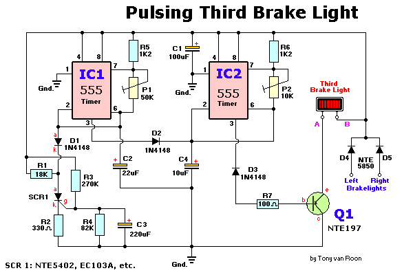
Pulsing Third Brake Light Circuit
Any type of flashing light on the main brake lights is prohibited and illegal in most states of the U.S.A. Verification is being conducted for the same in Canada. Meanwhile, using this circuit is at one's own risk, with awareness...
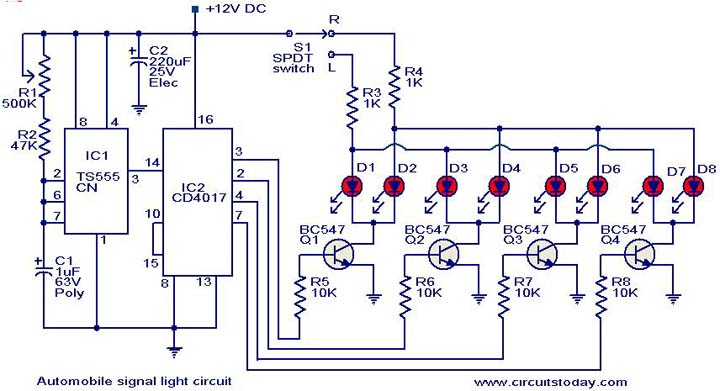
Automobile turn signal circuit
This is a simple circuit that can be used as a sequential signal light in automobiles. The circuit is based on two integrated circuits (ICs): a TS 555 CN CMOS timer IC and a CD4017 decade counter IC. The TS...
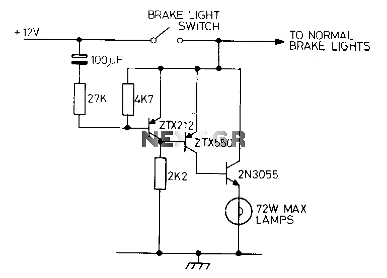
Delayed-extra-brake-light
Activating the brake pedal in a vehicle triggers the standard brake lights, followed by a delay before the additional lights are illuminated. A bimetal strip connected in series with the lights can create a flashing effect.
The described circuit operates on...
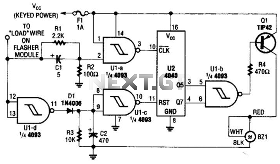
Auto Turn-Signal Reminder Circuit
This circuit counts the flashes of turn signals. After approximately 70 flashes, a chime sounds to remind the driver to deactivate the turn signal. The period can be altered by using different taps on U2 if desired. BZ1 serves as...

Brake Light Signal Module
Circuits of this type are designed to drive LED arrays to enhance visibility and conspicuity when a vehicle is stopped or slowing down. This specific circuit emits a visual alert signal consisting of four short flashes followed by a steady...
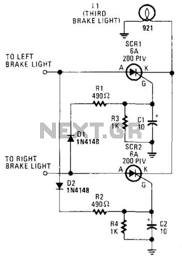
Third Brake Light
The circuit is designed to illuminate the third brake light (via SCR1 and SCR2) only when both the left and right brake lights are activated. The circuit operates on 12-V negative-ground systems. When the brake pedal is depressed, 12 V...
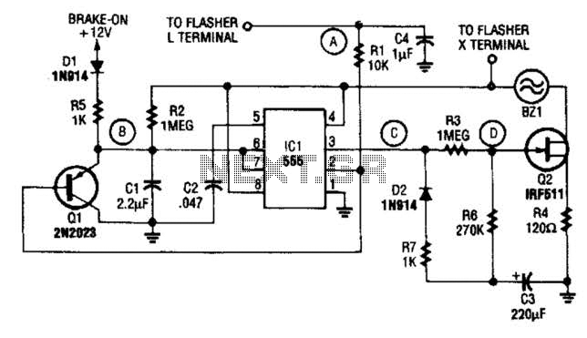
Smart Turn Signal Circuit
The STS schematic illustrates a circuit designed to alert a driver when the turn signal has been active for more than 15 seconds. The voltage at the gate of transistor Q2 increases in response to the charge accumulated on capacitor...
.png "One-touch turn signal module circuit")
One-touch turn signal module
The one-touch turn signal (OTTS) module enhances the functionality of the turn signal lever by introducing a mode where a single touch activates the indicators to blink for a specified number of times. This feature is commonly referred to as...
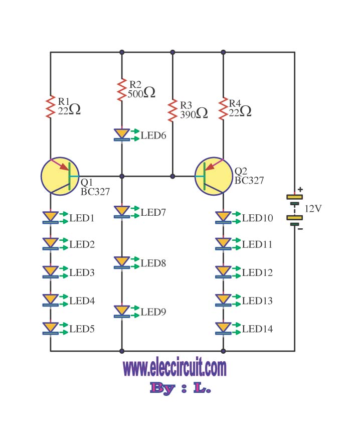
Brake lights flasher circuits
This circuit enables the brake light to flash. The default behavior occurs when power is supplied to the circuit or when the brake is engaged. The timer IC (IC2) drives current to the transistor (Q2), producing an oscillating output pulse...