


Self Parking Robot Car
#self-parking
#robot car
#sensors
#automation
#ultrasonic
#infrared
#microcontroller
#motor control
#parking system
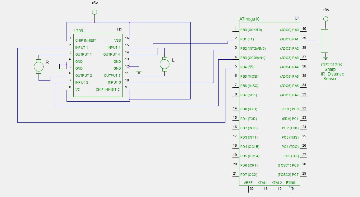
Description: Self-parking is an automatic parking system found in modern vehicles. It utilizes various sensors such as cameras, sonars, and infrared rangefinders to collect information about the vehicle's surroundings. Complex processing algorithms are then employed to park the vehicle without driver intervention. This system differs from parking assistant systems.
The self-parking system integrates multiple sensor technologies to create a comprehensive understanding of the vehicle's environment. Cameras provide visual input, enabling the system to detect obstacles, lane markings, and parking space dimensions. Sonar sensors emit sound waves to measure distances to nearby objects, while infrared rangefinders can detect proximity in low-light conditions.
The data gathered from these sensors is processed using sophisticated algorithms that analyze the vehicle's position and orientation in relation to potential parking spaces. The system calculates optimal maneuvers, including steering angles and throttle control, to execute parking maneuvers autonomously.
Control units within the vehicle process the sensor data in real-time, allowing for immediate adjustments to the vehicle's trajectory. The system typically includes fail-safe mechanisms to ensure safety during operation, such as automatic braking if an obstacle is detected during parking.
Self-parking technology enhances convenience for drivers, particularly in tight urban environments where parking can be challenging. It represents a significant advancement in automotive technology, contributing to the development of fully autonomous vehicles in the future.Self Parking is a automatic parking system found in modern cars. It makes use of various sensors like cameras, sonars, infrared rangefinders etc. to gather information about the surroundings of a car and then use complex processing algorithms to park the car without the help of the driver. It is different from parking assistant systems.
The self-parking system integrates multiple sensor technologies to create a comprehensive understanding of the vehicle's environment. Cameras provide visual input, enabling the system to detect obstacles, lane markings, and parking space dimensions. Sonar sensors emit sound waves to measure distances to nearby objects, while infrared rangefinders can detect proximity in low-light conditions.
The data gathered from these sensors is processed using sophisticated algorithms that analyze the vehicle's position and orientation in relation to potential parking spaces. The system calculates optimal maneuvers, including steering angles and throttle control, to execute parking maneuvers autonomously.
Control units within the vehicle process the sensor data in real-time, allowing for immediate adjustments to the vehicle's trajectory. The system typically includes fail-safe mechanisms to ensure safety during operation, such as automatic braking if an obstacle is detected during parking.
Self-parking technology enhances convenience for drivers, particularly in tight urban environments where parking can be challenging. It represents a significant advancement in automotive technology, contributing to the development of fully autonomous vehicles in the future.Self Parking is a automatic parking system found in modern cars. It makes use of various sensors like cameras, sonars, infrared rangefinders etc. to gather information about the surroundings of a car and then use complex processing algorithms to park the car without the help of the driver. It is different from parking assistant systems.
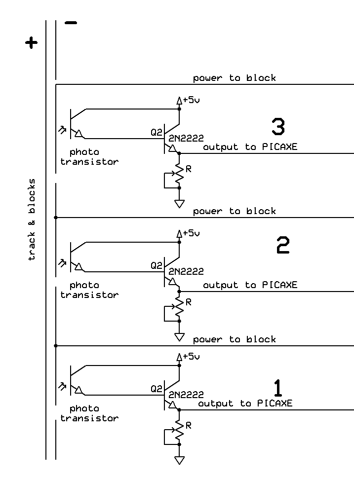
Automatic Switch Project 2
The switch control system utilizes sensors to inform the microcontroller of the trains' positions on the layout. This ensures that only one train occupies the main line at any given time and that switches are correctly set for the train's...
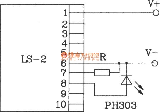
Direct infrared remote control switch circuit diagram composed of LS-2
The LS-2 remote control switch infrared sensor module is similar to the LS-18 but functions as a reflector. The LS-2 pin diagram and internal block diagram provide insights into its electrical parameters. The operating voltage for the LS-2 remote control...
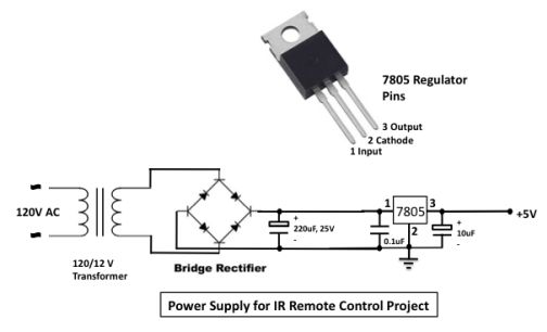
infrared toggle switch for home
The infrared (IR) toggle switch project aims to provide a control mechanism for electrical appliances lacking remote operation features. The objective is to create a device that allows users to plug in a 120V AC appliance and control its ON...
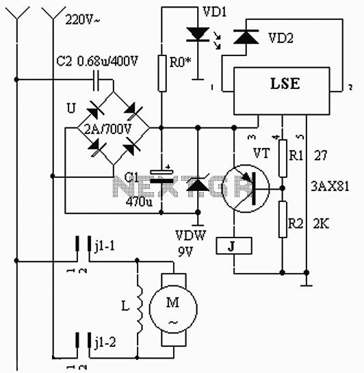
LES production with automatic hand controller circuit
The circuit operates based on the interaction between an infrared light-emitting diode (VD1) and an infrared receiver diode (VD2). When VD1 emits infrared radiation, it is detected by VD2, which causes a decrease in its internal resistance. This change results...
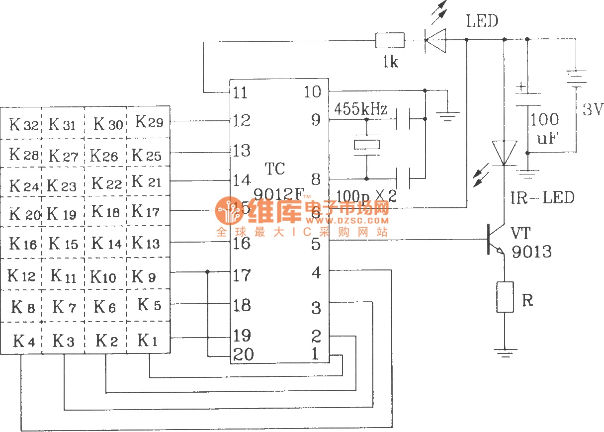
Typical infrared emission application circuit diagram composed of TC9012F
The TC9012 is a specialized off-screen remote control code transmitter. It incorporates an oscillator, divider timing generator, system code latch, data storage, key scan input, key scan output, and carrier control and output units. The internal 8-bit system code setting...
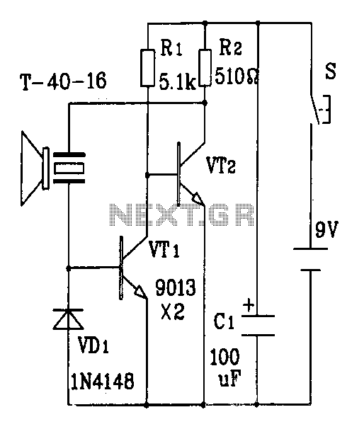
An ultrasonic transmitter circuit diagram discrete components
The discrete components ultrasonic transmitter circuit T/R-40-16 can emit a series of ultrasonic signals at a frequency of 40 kHz. This circuit operates at a voltage of 9V and has a current consumption of 25mA, with a control distance of...
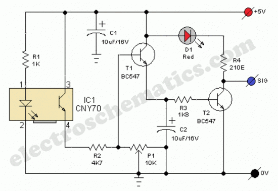
Line Following Robot Sensor
This line-following robot sensor or surface scanner for robots is a compact, stamp-sized infrared proximity detector designed for short-range detection (5-10 mm).
The line-following robot utilizes an infrared proximity sensor that detects the presence of surfaces or lines beneath it. This...
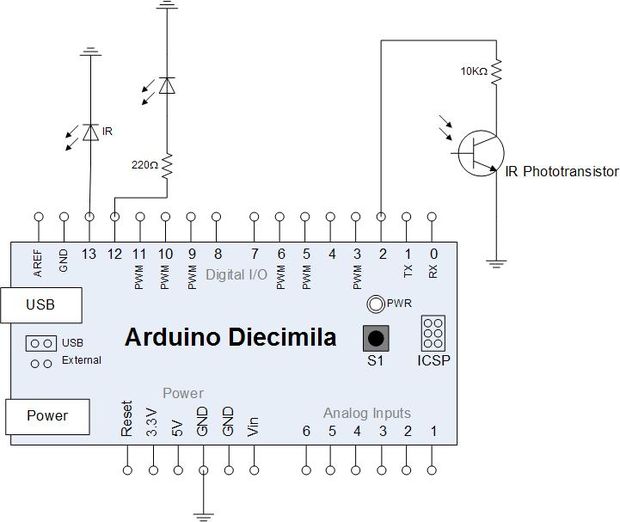
reading electricity meter ir impulses
Yesterday, an attempt was made to read the infrared impulses from an electricity meter using a phototransistor. The phototransistor can detect infrared signals from various remote controls in the house but fails to detect the blinking signal from the electricity...
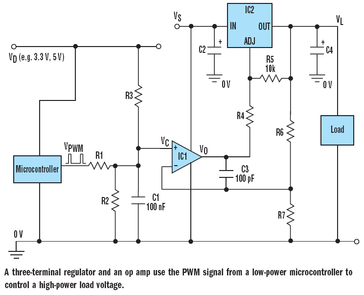
microcontroller How does this power supply circuit work? (MCU + LM317)
The filter consisting of resistors R1, R2, and capacitor C1 integrates the PWM waveform. The purpose of the operational amplifier appears to be that of a non-inverting amplifier, with the gain determined by resistors R6 and R7. However, the need...