


Speed alarm
#speed alarm
#engine rpm
#CMOS gate
#oscillator
#diode pump
#current limiting resistor
#rectified
#clipped voltage
#4011
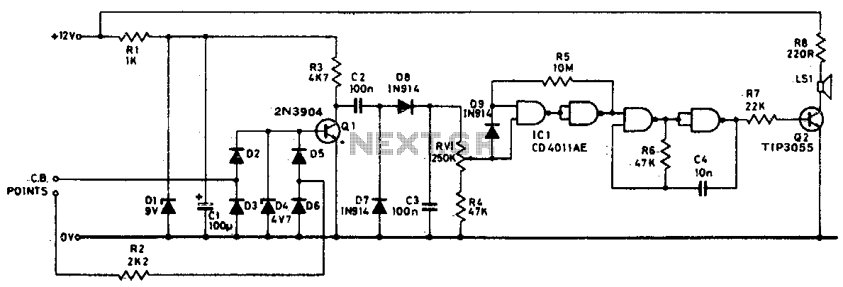
Description: Pulses from the distributor points are passed through a current-limiting resistor, rectified, and clipped at 4 volts. Through Q1 and the diode pump, a DC voltage proportional to engine RPM is presented to RV1. The sharp transfer characteristic of a CMOS gate, assisted by feedback, is utilized to enable the oscillator formed by the remaining half of the 4011. At the pre-set speed, a noticeable tone emits from the speaker and disappears as soon as the speed drops by three or four mph.
The described circuit functions as a speed detection and alert system for vehicles, utilizing the pulses generated by the distributor points as a primary input signal. The initial stage involves a current-limiting resistor that ensures the pulse amplitude is suitable for subsequent processing, protecting the components from excessive current. The pulses are then rectified, converting the AC signal into a DC voltage, which is further clipped to a maximum of 4 volts to maintain a consistent voltage level for downstream components.
The transistor Q1 acts as a switch, allowing the rectified voltage to be fed into a diode pump. This arrangement boosts the voltage to a level that is proportional to the engine RPM, which is then directed to RV1, a variable resistor that may be used to calibrate the sensitivity of the circuit.
The CMOS gate, known for its sharp transfer characteristics, plays a pivotal role in determining the output signal. Feedback is utilized to stabilize the oscillation, which is generated by the unused half of the 4011 quad NAND gate. This oscillator produces a tone that can be heard through a connected speaker, serving as an alert system for the driver.
The design includes a specific threshold speed, at which the tone becomes audible. This threshold is critical as it provides a clear indication to the driver when the vehicle reaches a pre-defined speed. If the vehicle's speed decreases by three or four mph from this threshold, the tone ceases, thereby providing an effective and simple means of speed monitoring. The overall circuit is compact and efficient, making it suitable for integration into various vehicle systems.Pulses from the distributor points are passed through a current limiting resistor, rectified, and clipped at 4 volts. Via Q1 and the diode pump, a dc voltage proportional to engine rpm is presented to RV1; the sharp transfer characteristic of a CMOS gate, assisted by feedback, is used to enable the oscillator formed by the remaining half of the 4011
At the pre-set speed, a nonignorable tone emits from the speaker, and disappears as soon as the speed drops by three or four mph.
The described circuit functions as a speed detection and alert system for vehicles, utilizing the pulses generated by the distributor points as a primary input signal. The initial stage involves a current-limiting resistor that ensures the pulse amplitude is suitable for subsequent processing, protecting the components from excessive current. The pulses are then rectified, converting the AC signal into a DC voltage, which is further clipped to a maximum of 4 volts to maintain a consistent voltage level for downstream components.
The transistor Q1 acts as a switch, allowing the rectified voltage to be fed into a diode pump. This arrangement boosts the voltage to a level that is proportional to the engine RPM, which is then directed to RV1, a variable resistor that may be used to calibrate the sensitivity of the circuit.
The CMOS gate, known for its sharp transfer characteristics, plays a pivotal role in determining the output signal. Feedback is utilized to stabilize the oscillation, which is generated by the unused half of the 4011 quad NAND gate. This oscillator produces a tone that can be heard through a connected speaker, serving as an alert system for the driver.
The design includes a specific threshold speed, at which the tone becomes audible. This threshold is critical as it provides a clear indication to the driver when the vehicle reaches a pre-defined speed. If the vehicle's speed decreases by three or four mph from this threshold, the tone ceases, thereby providing an effective and simple means of speed monitoring. The overall circuit is compact and efficient, making it suitable for integration into various vehicle systems.Pulses from the distributor points are passed through a current limiting resistor, rectified, and clipped at 4 volts. Via Q1 and the diode pump, a dc voltage proportional to engine rpm is presented to RV1; the sharp transfer characteristic of a CMOS gate, assisted by feedback, is used to enable the oscillator formed by the remaining half of the 4011
At the pre-set speed, a nonignorable tone emits from the speaker, and disappears as soon as the speed drops by three or four mph.
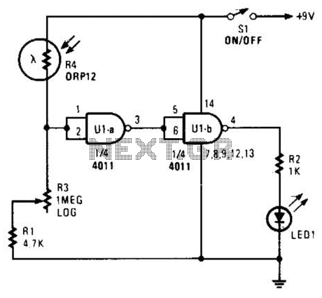
Enlarger Exposure Meter Circuit
Two gates of a 4011 IC are utilized as a comparator. When the resistance of R4 decreases, the voltage at pins 1 and 2 increases, resulting in a logic zero at pin 3. This causes pin 4 to go high,...

Double oscillator metal detector
The circuit consists of two oscillators, both working at about 465 kHz. One uses an if transformer and the other uses an inductor (the search coil LI). The oscillators are coupled by a capacitor (10 pF). A beat note (produced...
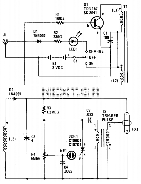
Safety flare
When the switch SI is activated, power is supplied to an oscillator that consists of Q1, R1, C1, L1, and L2. Coil L1 serves as the primary winding of transformer T1, while L2 functions as the feedback winding. As Q1...

Stable Start-Stop Oscillator
Oscillators that generate a predetermined number of pulses are often required in applications such as video work. This oscillator starts 13 ms after the control signal goes high and stops immediately when the input signal goes low.
In electronic applications, pulse...
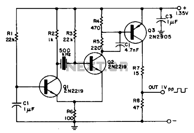
Oscillator operates from one cell
The circuit is powered by a single 1.35 V mercury cell and provides a 1 V square-wave output. The crystal acts as a tuned circuit between transistors Q1 and Q2, which are connected in a common-emitter configuration. Positive feedback is...

Little dipper
The circuit consists of two fundamental components: the oscillator and the detector. The oscillator employs a Field Effect Transistor (FET) in a Colpitts configuration. The energy circulating within the oscillator's tank is coupled through capacitor C4 to the detector circuit,...
small general purpose audio
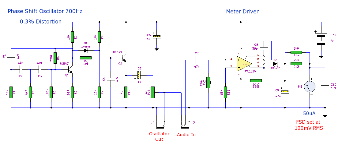
This is a compact general-purpose audio test set. It includes a low distortion (0.3%) phase shift oscillator and a level meter. The level meter is calibrated at 100mV full scale deflection (FSD) and is suitable for gain measurements and general...
Variable Duty-Cycle Oscillator Circuit
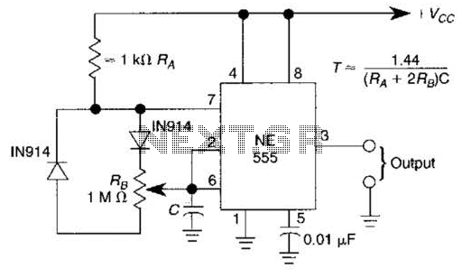
A 1.2-kHz oscillator utilizing a potentiometer and steering diodes allows for a duty cycle adjustment ranging from 1% to 99%. The frequency can be altered by varying the capacitor CI. It is important to note that the diodes may slightly...
Oscillator IIV
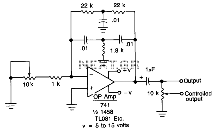
When the oscillator is connected to a DC circuit, a DC blocking capacitor should be connected in series with the potentiometer's wiper arm. For finer output control, a 10 kΩ potentiometer can be added.
In this circuit configuration, the oscillator generates...