


Time-Delay Auto-Kill Switch Circuit
#time-delay
#auto-kill switch
#relay
#ignition
#starter solenoid
#automotive security
#pushbutton switch
#delay circuit
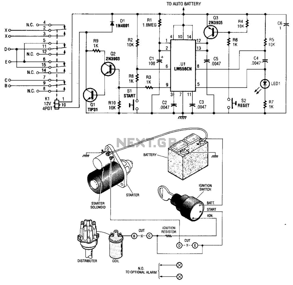
Description: The automobile delayed kill switch operates on a straightforward principle. Upon exiting the vehicle, a hidden pushbutton switch is activated. Although no immediate effect is visible, after a preset duration, a relay engages and locks in place. This action results in the opening of contacts, which disconnects the power supply from the ignition coil and the key switch to the starter solenoid. Consequently, if the engine is running, it will stop abruptly, and the starter will become inoperative. Re-entering the vehicle and pressing another pushbutton switch causes the relay to disengage, restoring normal functionality.
The automobile delayed kill switch is a safety mechanism designed to prevent unauthorized use of the vehicle by disabling the ignition system after a specified delay. This system can be implemented using a combination of electronic components, including a pushbutton switch, a timer circuit, and a relay.
The hidden pushbutton switch, which is activated when the driver exits the vehicle, is typically connected to a timer circuit. This circuit can be designed using a 555 timer IC in monostable mode, which provides a time delay before sending a signal to the relay. The time duration can be adjusted by changing the resistor and capacitor values in the timer circuit, allowing for customization based on user preference.
Once the timer expires, it triggers a relay that has normally open (NO) and normally closed (NC) contacts. The NO contacts are connected to the ignition system, specifically the wire leading to the ignition coil and the starter solenoid. When the relay is activated, it opens the circuit, effectively cutting off power to these components. This action ensures that if the engine is still running, it will cease operation immediately, and the starter will not engage, preventing any attempt to restart the engine while the kill switch is active.
To restore normal operation, a second pushbutton switch is installed inside the vehicle. Pressing this switch closes the relay circuit, returning the ignition system to its operational state. This two-switch mechanism enhances security, as both switches must be activated in their respective locations to enable the vehicle's ignition system.
In summary, the automobile delayed kill switch is an effective anti-theft device that employs a timer, pushbutton switches, and a relay to control the ignition system, ensuring that the vehicle cannot be easily restarted once the driver exits. The design can be further enhanced with additional features, such as LED indicators to show the status of the kill switch or a more sophisticated microcontroller for timing and control functions. The automobile delayed kill switch is simple in concept. When you get out of your car, a secretly located pushbutton switch is pressed. Nothing apparently happens, but at the end of a predetermined time, a relay is pulled in and locked. When the relay is pulled in, contacts open, and the hot lead from the ignition to the coil and the hot wire from the key switch to the starter solenoid is opened or disconnected. If the engine is running, it stops immediately and the starter will not operate. When you get into the car, another pushbutton switch is pressed and the relay drops out and everything goes back to normal.
The automobile delayed kill switch is a safety mechanism designed to prevent unauthorized use of the vehicle by disabling the ignition system after a specified delay. This system can be implemented using a combination of electronic components, including a pushbutton switch, a timer circuit, and a relay.
The hidden pushbutton switch, which is activated when the driver exits the vehicle, is typically connected to a timer circuit. This circuit can be designed using a 555 timer IC in monostable mode, which provides a time delay before sending a signal to the relay. The time duration can be adjusted by changing the resistor and capacitor values in the timer circuit, allowing for customization based on user preference.
Once the timer expires, it triggers a relay that has normally open (NO) and normally closed (NC) contacts. The NO contacts are connected to the ignition system, specifically the wire leading to the ignition coil and the starter solenoid. When the relay is activated, it opens the circuit, effectively cutting off power to these components. This action ensures that if the engine is still running, it will cease operation immediately, and the starter will not engage, preventing any attempt to restart the engine while the kill switch is active.
To restore normal operation, a second pushbutton switch is installed inside the vehicle. Pressing this switch closes the relay circuit, returning the ignition system to its operational state. This two-switch mechanism enhances security, as both switches must be activated in their respective locations to enable the vehicle's ignition system.
In summary, the automobile delayed kill switch is an effective anti-theft device that employs a timer, pushbutton switches, and a relay to control the ignition system, ensuring that the vehicle cannot be easily restarted once the driver exits. The design can be further enhanced with additional features, such as LED indicators to show the status of the kill switch or a more sophisticated microcontroller for timing and control functions. The automobile delayed kill switch is simple in concept. When you get out of your car, a secretly located pushbutton switch is pressed. Nothing apparently happens, but at the end of a predetermined time, a relay is pulled in and locked. When the relay is pulled in, contacts open, and the hot lead from the ignition to the coil and the hot wire from the key switch to the starter solenoid is opened or disconnected. If the engine is running, it stops immediately and the starter will not operate. When you get into the car, another pushbutton switch is pressed and the relay drops out and everything goes back to normal.
Sound-Controlled Relay
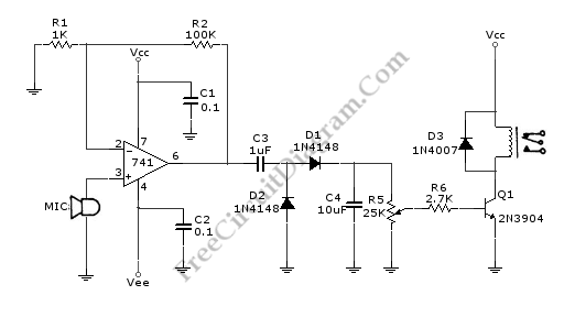
This is a relay circuit that detects the presence of sound to activate the relay. This sound-controlled relay can be utilized as a voice-operated switch or for controlling lights.
The sound-activated relay circuit typically employs a microphone or a sound sensor...
Multi-spark for Electronic Ignition
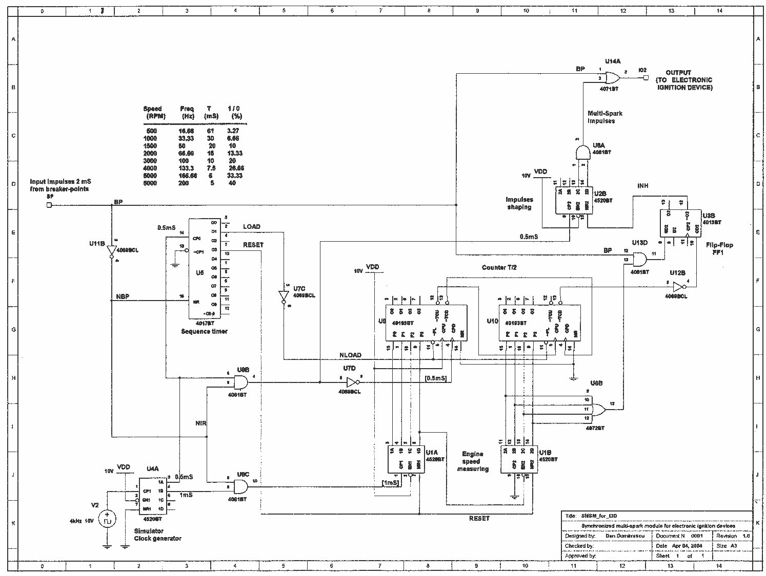
Multi-spark ignition is very useful especially in the case of startings at low temperature and at low rpm range. Basic idea, is to apply to spark plugs instead of only one spark, a spark-burst having big energy. In this case,...
Relay pull-in timer circuit in time process
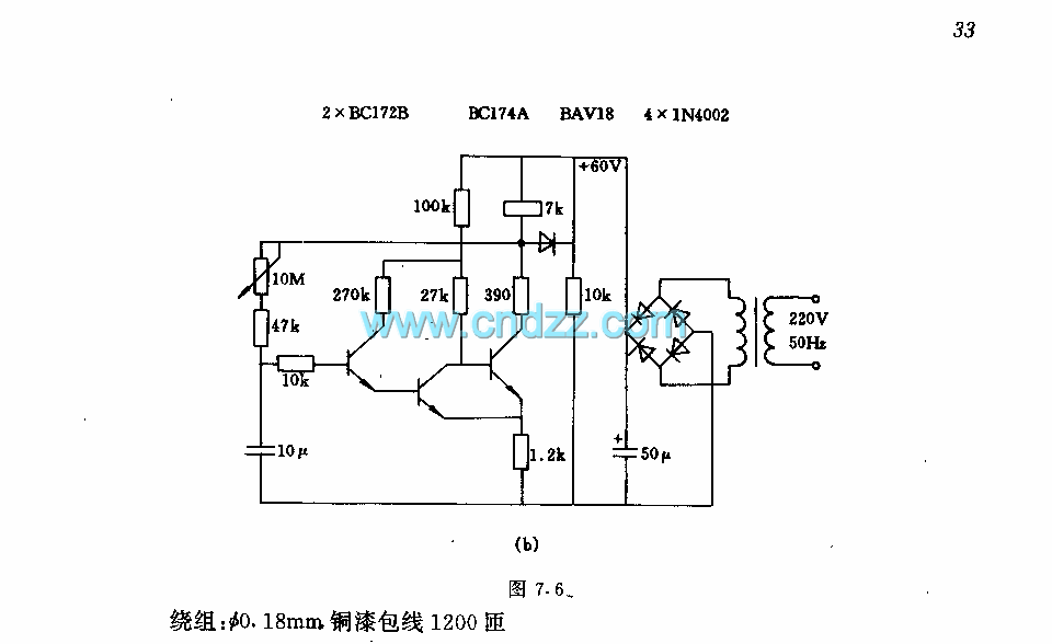
The circuit features a two-stage structure with a timing range of approximately 0.5 to 12 seconds, while in a specified configuration, the timing range extends from 1 to 160 seconds. The transformer parameters include an iron core made of M42/15.7...
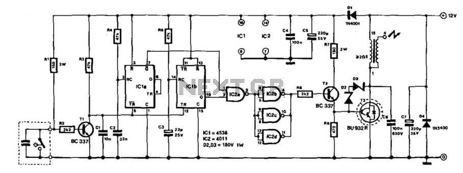
Electronic Ignition
This electronic ignition circuit is designed to be integrated into a conventional car ignition system. It replaces the original 12-V switching circuit in the primary winding of the ignition coil with a circuit that generates over 100 V. This modification...
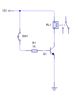
switches Can I achieve a one shot button without a 555
A relay is activated by grounding the low side using an NPN transistor. A pushbutton is intended to operate the transistor, thereby energizing the relay for approximately 500 milliseconds before deactivating it, while ignoring any continuous button press. Although timers...
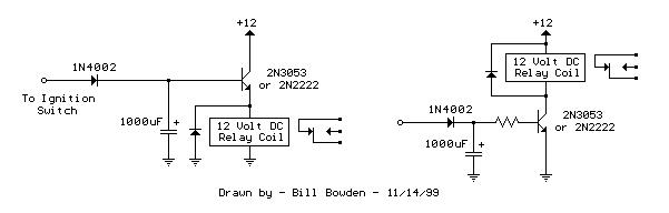
power off time delay relay
The two circuits demonstrate the process of opening a relay contact shortly after the ignition or light switch is turned off. The capacitor becomes charged, and the relay remains closed until the voltage at the diode anode reaches +12 volts.
The...
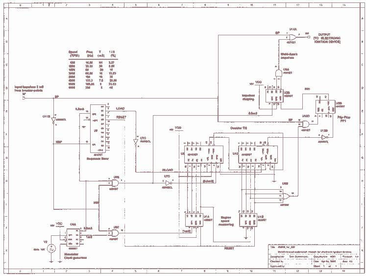
Multi-spark module for Electronic Ignition
Multi-spark ignition is very useful especially in the case of startings at low temperature and at low rpm range. Basic idea, is to apply to spark plugs instead of only one spark, a spark-burst having big energy. In this case,...
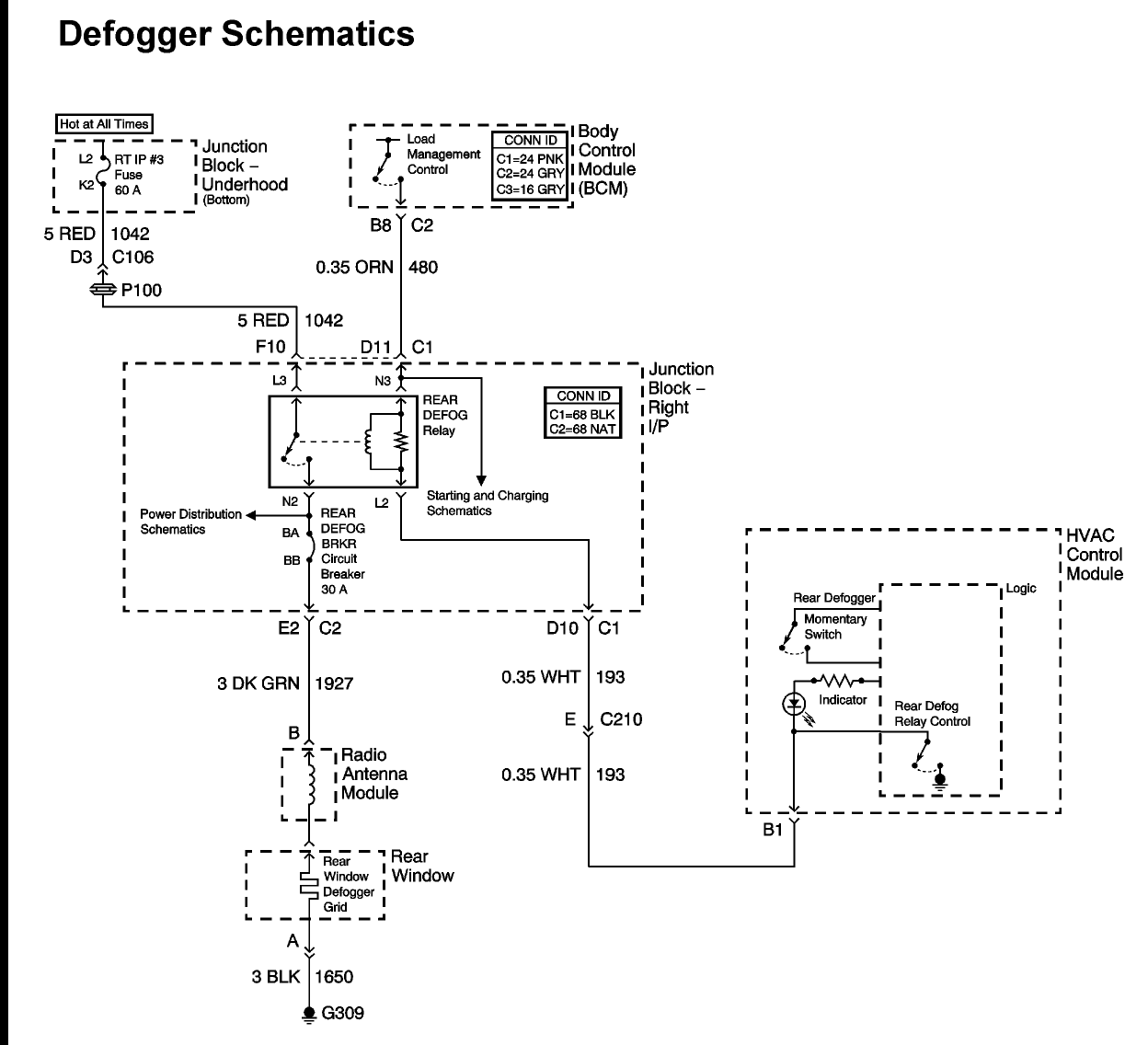
2004 chevy impala: relay diagram passenger side fuse block
A 2004 Chevrolet Impala is experiencing issues with the rear defogger. The owner is unable to locate the fuse for the rear defogger, although the relay has been found. Both the manual and the vehicle's diagram indicate a 30-amp fuse,...
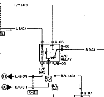
relay Do I need a protection diode here
An automotive relay is being analyzed, which exhibits a more complex wiring configuration than typical relays. The diagram indicates that the B/G line maintains a high signal if certain conditions are met, specifically when the engine temperature is excessively high,...