


Toyota MR2 Power Steering System
#power steering
#motor control
#Toyota MR2
#noise reduction
#energy efficiency
#automotive electronics
#pump control
#custom controller
#vehicle modification
#power management
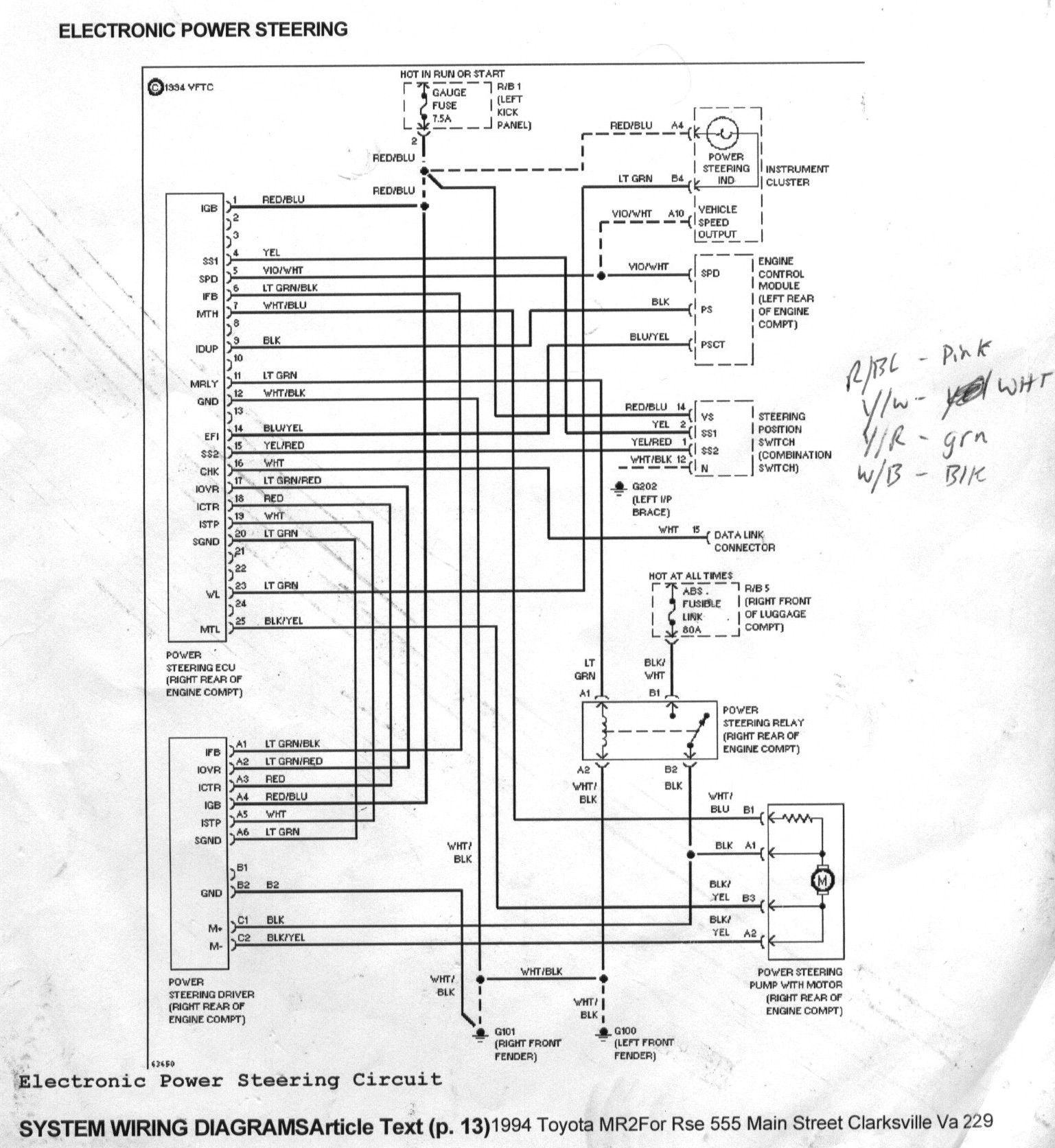
Description: The goal was to control the MR2 power steering pump to reduce noise and power consumption, as it operates at full throttle continuously. Designing a custom motor controller was not feasible due to a lack of expertise, and off-the-shelf controllers were unsuitable for high voltage systems. The decision was made to salvage the original motor controller from an MR2 at a junkyard. This approach yielded better results than expected. One feature of the MR2 controller allows the hydraulic pump to stop when there is no steering wheel movement or vehicle speed, conserving power. The system was wired to activate when the Zilla contactor is engaged, utilizing the original MR2 steering wheel sensor to detect steering input. Additionally, road speed information from the cruise control speed sensor was incorporated to prevent over-steering at high speeds. The system also monitors the hydraulic pump's sensors for brush wear or overheating. The provided power steering schematics are from 1994 and 1995 MR2 models, and it is recommended to obtain components from similar model years. Several schematic versions are available, allowing selection based on specific needs. The original cruise control speed sensor from an 1985 S10 was used to drive the ECU, yielding satisfactory results, although pulse rates may vary. The ICT (PSCT) wire connects to the main engine ECU to enable power steering when the engine is running; grounding this wire disables the power steering ECU. A micro relay and a 1K Ohm resistor were employed to keep this wire grounded until the main contactor is engaged, with the small relay connected in parallel with the main contactor, which the Zilla system accommodates without issues. The hydraulic pump from a different model year had only three sensor wires, missing the V-L (Violet/Light Stripe) wire, which was easily remedied after testing.
The MR2 power steering pump control system integrates several components and sensors to optimize performance while reducing energy consumption and noise. The original MR2 motor controller is central to this design, featuring an automatic shut-off function that halts the hydraulic pump when steering input is absent or the vehicle is stationary. This feature significantly enhances efficiency by preventing unnecessary power draw.
The system utilizes a Zilla contactor to engage the power steering only when required. The engagement of the contactor activates the original MR2 controller, which in turn powers the hydraulic pump. The integration of the steering wheel sensor allows the controller to adjust the pump's output based on the driver's steering input, providing responsive steering assistance. The road speed information from the cruise control sensor is critical for limiting the pump's output at higher speeds, thereby preventing oversteering and enhancing vehicle stability.
The monitoring of the hydraulic pump's operational status is achieved through built-in sensors that detect brush wear and overheating conditions, allowing for timely maintenance and ensuring the longevity of the pump. The power steering schematics from the 1994 and 1995 MR2 models provide a reliable reference for wiring and component selection, ensuring compatibility and functionality.
In implementing this control system, careful attention was paid to the ICT (PSCT) control wire, which interfaces with the main engine ECU. This wire must be grounded to disable the power steering ECU when the engine is not running. The use of a micro relay and a resistor ensures that the wire remains grounded until the main contactor is engaged, allowing for seamless operation of the power steering system.
Overall, this comprehensive approach to controlling the MR2 power steering pump effectively balances performance, efficiency, and reliability, making it a valuable enhancement for vehicle systems.Wondered how to control the MR2 Power steering pump so that it is not a noisy power hog because it ’s always on full throttle. Designing some sort of motor controller or using a small off-the-shelf controller would not work for me.
One, I ’m not that great of a designer of controllers (I ’ll leave this up to Otmar). Second, a small of f-the-shelf controller would not work on high voltage systems. Plus, I would have to program some type of Micro or Basic Stamp to get all the functions I want. So I decided to get the original motor controller from a MR2 at the junk yard and try to wire it up. Well, it works better than I anticipated. One of the modes of the MR2 controller is to slow the hydraulic pump to a stop when there is no movement of the steering wheel or vehicle road speed: saves power! I have also wired it to enable itself when the Zilla Contactor is engaged. I`m using the original steering wheel sensor from the MR2, so it senses how much steering I`m applying.
It is also getting road speed info from the cruise control speed sensor to limit over-steer at high road speeds. It uses the sensors in the pump to tell you when the brushes are worn or overheated. The P. S. schematics provided are from a ’94 and ‘95 MR2, so try and get all the parts from a Toyota close as possible to these years.
There are a couple different versions of the schematics here, so use the one that best suits your needs. 1. I used the original cruise control speed sensor for my ’85 S10 to drive the ECU and it has worked with good results.
Your results or pulse rates may vary. 2. The ICT (PSCT) is a control wire for the main engine ECU to enable the P. S. when the engine is running. The P. S. ECU is disabled when this wire is brought low (grounded). So I used a micro-sized relay and a 1K Ohm resister to keep this wire low until the main contactor is engaged. I hooked the small relay in parallel with main contactor. My Zilla has no problem with this. 3. My Hydraulic pump was from a slightly different year so it had only 3 sensor wires. After some testing I realized that it was missing the V-L or Violet/Light Stripe wire. Look at the schematic and you will see how easy this was fixed.
The MR2 power steering pump control system integrates several components and sensors to optimize performance while reducing energy consumption and noise. The original MR2 motor controller is central to this design, featuring an automatic shut-off function that halts the hydraulic pump when steering input is absent or the vehicle is stationary. This feature significantly enhances efficiency by preventing unnecessary power draw.
The system utilizes a Zilla contactor to engage the power steering only when required. The engagement of the contactor activates the original MR2 controller, which in turn powers the hydraulic pump. The integration of the steering wheel sensor allows the controller to adjust the pump's output based on the driver's steering input, providing responsive steering assistance. The road speed information from the cruise control sensor is critical for limiting the pump's output at higher speeds, thereby preventing oversteering and enhancing vehicle stability.
The monitoring of the hydraulic pump's operational status is achieved through built-in sensors that detect brush wear and overheating conditions, allowing for timely maintenance and ensuring the longevity of the pump. The power steering schematics from the 1994 and 1995 MR2 models provide a reliable reference for wiring and component selection, ensuring compatibility and functionality.
In implementing this control system, careful attention was paid to the ICT (PSCT) control wire, which interfaces with the main engine ECU. This wire must be grounded to disable the power steering ECU when the engine is not running. The use of a micro relay and a resistor ensures that the wire remains grounded until the main contactor is engaged, allowing for seamless operation of the power steering system.
Overall, this comprehensive approach to controlling the MR2 power steering pump effectively balances performance, efficiency, and reliability, making it a valuable enhancement for vehicle systems.Wondered how to control the MR2 Power steering pump so that it is not a noisy power hog because it ’s always on full throttle. Designing some sort of motor controller or using a small off-the-shelf controller would not work for me.
One, I ’m not that great of a designer of controllers (I ’ll leave this up to Otmar). Second, a small of f-the-shelf controller would not work on high voltage systems. Plus, I would have to program some type of Micro or Basic Stamp to get all the functions I want. So I decided to get the original motor controller from a MR2 at the junk yard and try to wire it up. Well, it works better than I anticipated. One of the modes of the MR2 controller is to slow the hydraulic pump to a stop when there is no movement of the steering wheel or vehicle road speed: saves power! I have also wired it to enable itself when the Zilla Contactor is engaged. I`m using the original steering wheel sensor from the MR2, so it senses how much steering I`m applying.
It is also getting road speed info from the cruise control speed sensor to limit over-steer at high road speeds. It uses the sensors in the pump to tell you when the brushes are worn or overheated. The P. S. schematics provided are from a ’94 and ‘95 MR2, so try and get all the parts from a Toyota close as possible to these years.
There are a couple different versions of the schematics here, so use the one that best suits your needs. 1. I used the original cruise control speed sensor for my ’85 S10 to drive the ECU and it has worked with good results.
Your results or pulse rates may vary. 2. The ICT (PSCT) is a control wire for the main engine ECU to enable the P. S. when the engine is running. The P. S. ECU is disabled when this wire is brought low (grounded). So I used a micro-sized relay and a 1K Ohm resister to keep this wire low until the main contactor is engaged. I hooked the small relay in parallel with main contactor. My Zilla has no problem with this. 3. My Hydraulic pump was from a slightly different year so it had only 3 sensor wires. After some testing I realized that it was missing the V-L or Violet/Light Stripe wire. Look at the schematic and you will see how easy this was fixed.
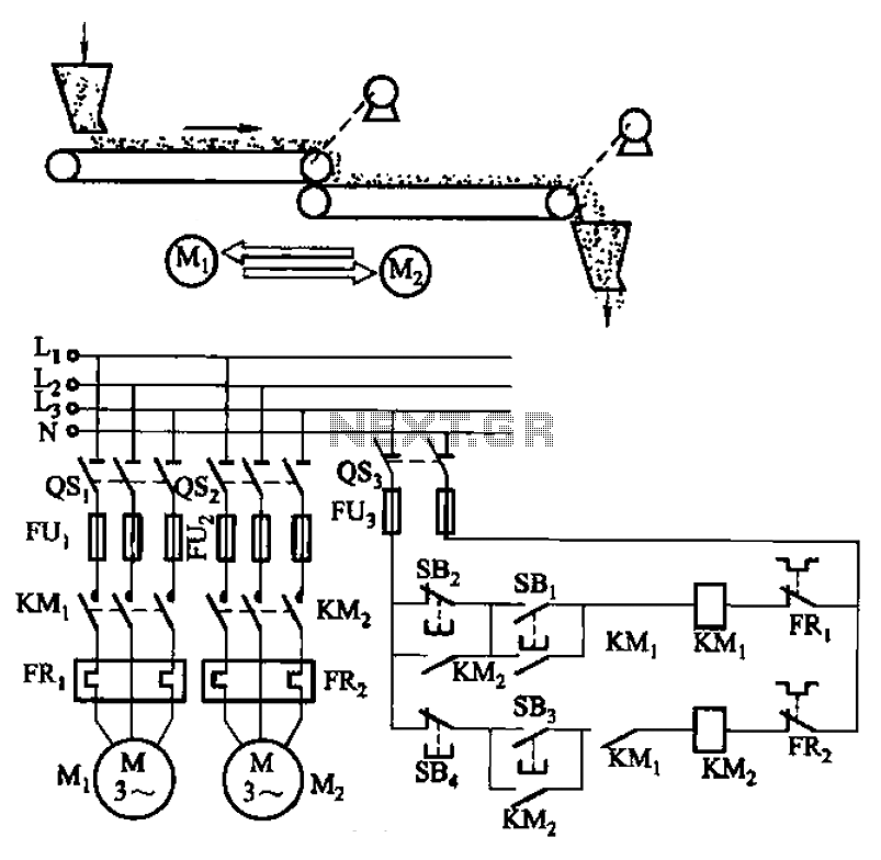
Belt conveyor interlock motor operation sequence control circuit
The circuit depicted in Figure 3-86 utilizes a line utilization time relay to control two motors, starting one before the other after an initial stall. The time relay KTi can be adjusted to modify the starting interval of the two...
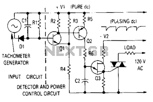
Motor control with tachometer
The generator output is rectified, filtered, and applied between the positive supply voltage and the base of the detector transistor. This configuration provides a negative voltage that reduces the base voltage as the speed increases. During normal operation, if the...
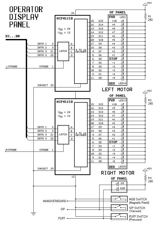
Dual-Motor SIP&PUFF Controlled Kayak System
The YouTube video below demonstrates the quick and easy setup of the system at the launch site.
The provided description indicates a focus on the efficiency of system installation at a launch site, as showcased in a YouTube video. In an...
Gray Projects
After learning to operate the device, it became evident that inertia posed a significant challenge. The constructed system is notably heavy, making it difficult to initiate motor operation at full speed. Despite having some understanding of physics, practical experience is...
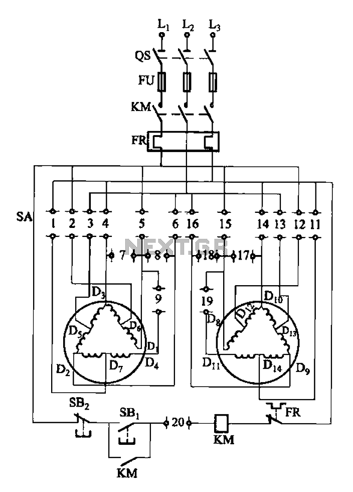
2Y-Y-2 - connection four-speed motor switch control circuit
The 3-119 circuit shown in the figure combines switch SA to realize the stator windings, specifically the 2, Y, and 2Y connections, which correspond to the motor speed n1.
The 3-119 circuit is designed to facilitate the control of motor speed...
Motorized Video Camera Mount
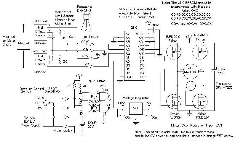
The camera rotator circuit utilizes a 2716 EPROM to store a logic value table that governs the motor driver (H-bridge) circuit. The schematic illustrates the EPROM data. By employing the EPROM, a significant number of discrete gates are eliminated. The...
My Motors got me to Tap into Radiant Energy
A new user is seeking to share information about their experiences on this platform.
The user expresses a desire to communicate and engage with the community regarding their experiences. This indicates an interest in exchanging knowledge and possibly seeking assistance or...
2Y-Y-2 - connection four-speed motor switch control circuit
The 3-119 circuit shown in the figure combines switch SA to realize the stator windings, specifically the 2, Y, and 2Y connections, which correspond to the motor speed n1.
The 3-119 circuit is designed to facilitate the control of motor speed...
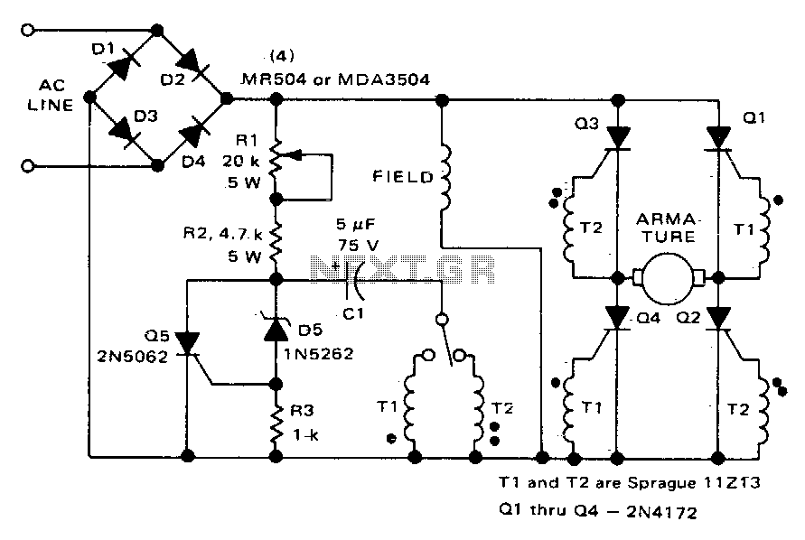
Direction and speed control
This circuit functions similarly to the one depicted in Fig. 57-4. The key differences include the placement of the field across the rectified supply and the armature being positioned within the SCR bridge. Therefore, the field current is unidirectional while...