


Vire 7 Starter GeneratorCircuits
#starter-generator
#Bosch
#Delco-Remy
#automotive
#circuit diagrams
#electrical systems
#vehicle electronics
#engine starting
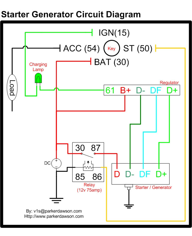
Description: Circuit diagrams for both a Bosch and a Delco-Remy Starter-Generator are available, noting that the circuits differ. Due to a computer crash, the original diagrams and the associated email address were lost. However, in May 2004, both the email and the diagrams were recovered. Acknowledgment is given to Sampo for assistance, despite the delay. Additionally, a month after recovering the scanned images, a schematic was obtained from Vis, the Webmaster, which features a circuit with separate starter relays and voltage regulators. The cross-section of the cables indicated by the thinner lines in the diagram is 2.5 sq. mm (0.0039 sq. in), while the thicker lines represent a cross-section of 16 sq. mm (0.025 sq. in).
The circuit diagrams for the Bosch and Delco-Remy Starter-Generators serve as essential references for understanding the electrical configurations and operational functionalities of these starter systems. Each diagram is tailored to the specific characteristics of the respective starter-generator, highlighting the differences in circuit design and component integration.
The Bosch Starter-Generator circuit typically incorporates a robust starter relay, which is responsible for engaging the starter motor, and a voltage regulator that stabilizes the output voltage to the battery and electrical system. The design ensures that the starter motor receives adequate power to initiate engine cranking while preventing overvoltage conditions that could damage sensitive electronic components.
Conversely, the Delco-Remy Starter-Generator circuit may feature a slightly different arrangement of relays and voltage regulation mechanisms, reflecting variations in design philosophy and operational requirements. This circuit also emphasizes the importance of reliable connections and component ratings to ensure the efficient functioning of the starter-generator system.
The schematic provided includes detailed annotations regarding the cross-sectional areas of the cables used in the circuit. The thinner lines, representing cables with a cross-section of 2.5 sq. mm, are typically utilized for lower current applications, such as signal wiring or control circuits. In contrast, the thicker lines, indicating a cross-section of 16 sq. mm, are designated for high current paths, such as those connecting the starter motor and battery, ensuring minimal voltage drop and heat generation during operation.
Understanding these diagrams is crucial for technicians and engineers involved in the maintenance and repair of automotive electrical systems, as they provide a clear visual representation of the interconnections and component specifications necessary for troubleshooting and effective system management.Circuit diagrams for both a Bosch and a Delco-Remy Starter-Generator (yes, the circuits are different). Unfortunately, due to a computer crash, I lost both the diagrams and his E-mail address. However, I was able to recover the E-mail and the diagram in May 2004, so here they are, at the bottom of the page.
A big "Thank you" to Sampo, two years behind schedule! A month after recovering the scanned images, I also recovered a diagram sent to me by Vis, the Webmaster at. It`s a schematic of a circuit with separate starter relays and voltage regulators. Thanks Vis. The cross section of the cables indicated by the thinner lines in the diagram is 2. 5 sq. mm (0. 0039 sq. in). The cross section of the cables indicated by the thicker lines is 16 sq. mm (0. 025 sq. in).
The circuit diagrams for the Bosch and Delco-Remy Starter-Generators serve as essential references for understanding the electrical configurations and operational functionalities of these starter systems. Each diagram is tailored to the specific characteristics of the respective starter-generator, highlighting the differences in circuit design and component integration.
The Bosch Starter-Generator circuit typically incorporates a robust starter relay, which is responsible for engaging the starter motor, and a voltage regulator that stabilizes the output voltage to the battery and electrical system. The design ensures that the starter motor receives adequate power to initiate engine cranking while preventing overvoltage conditions that could damage sensitive electronic components.
Conversely, the Delco-Remy Starter-Generator circuit may feature a slightly different arrangement of relays and voltage regulation mechanisms, reflecting variations in design philosophy and operational requirements. This circuit also emphasizes the importance of reliable connections and component ratings to ensure the efficient functioning of the starter-generator system.
The schematic provided includes detailed annotations regarding the cross-sectional areas of the cables used in the circuit. The thinner lines, representing cables with a cross-section of 2.5 sq. mm, are typically utilized for lower current applications, such as signal wiring or control circuits. In contrast, the thicker lines, indicating a cross-section of 16 sq. mm, are designated for high current paths, such as those connecting the starter motor and battery, ensuring minimal voltage drop and heat generation during operation.
Understanding these diagrams is crucial for technicians and engineers involved in the maintenance and repair of automotive electrical systems, as they provide a clear visual representation of the interconnections and component specifications necessary for troubleshooting and effective system management.Circuit diagrams for both a Bosch and a Delco-Remy Starter-Generator (yes, the circuits are different). Unfortunately, due to a computer crash, I lost both the diagrams and his E-mail address. However, I was able to recover the E-mail and the diagram in May 2004, so here they are, at the bottom of the page.
A big "Thank you" to Sampo, two years behind schedule! A month after recovering the scanned images, I also recovered a diagram sent to me by Vis, the Webmaster at. It`s a schematic of a circuit with separate starter relays and voltage regulators. Thanks Vis. The cross section of the cables indicated by the thinner lines in the diagram is 2. 5 sq. mm (0. 0039 sq. in). The cross section of the cables indicated by the thicker lines is 16 sq. mm (0. 025 sq. in).
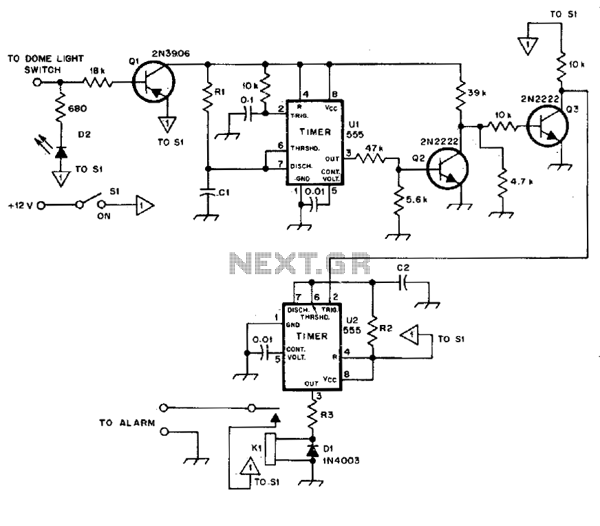
Automotive burglar alarm
The alarm activates after a 13-second delay and remains active for 1 to 1.5 minutes before automatically resetting. It can also be deactivated and reset by opening and reclosing switch SI.
The described circuit functions as a delay-triggered alarm system, incorporating...
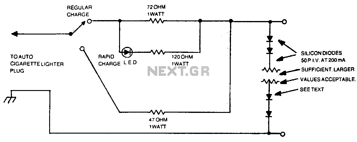
Automotive charger for ni-cad battery packs
The number of silicon diodes across the output is determined by the voltage of the battery pack. Each diode is considered at 0 volts. For example, a 10-volt pack would require 10/0 = 157, or 16 diodes.
In the context of...
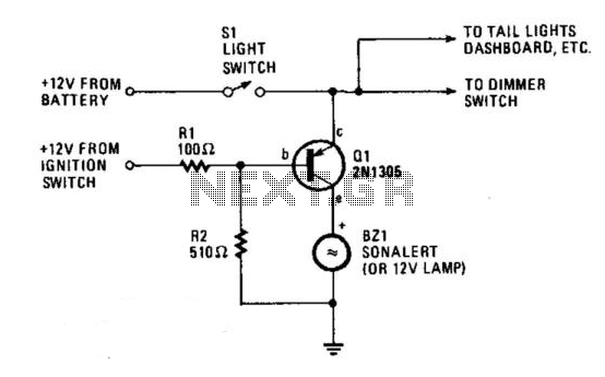
Automobile Lights-On Reminder
The circuit provides a visible or audible warning when the headlights are on. It utilizes a 2N1305 transistor as a switch to activate either a Sonalert tone generator or a small 12-V lamp. The operating current for the transistor is...
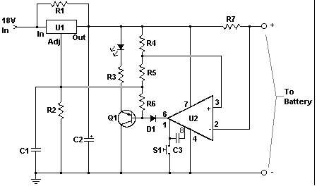
Car battery charger Automative car and motorcycle schematics
The circuit is designed to operate with an external power supply, which is why it does not include a transformer, rectifier, or filter capacitors in the schematic. However, these components can be added if desired. To utilize the circuit, connect...
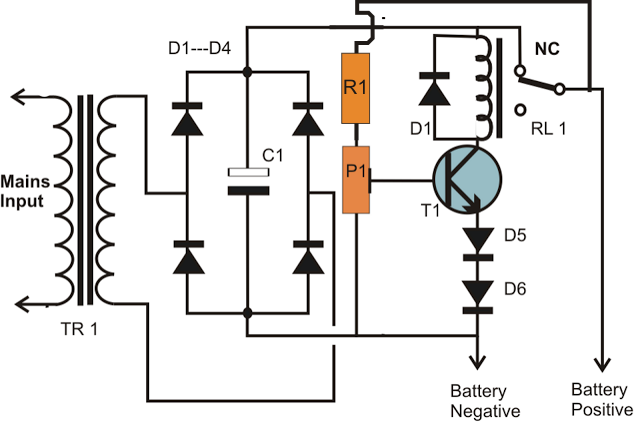
simplest smf automotive battery charger
A simple battery charger circuit is described, utilizing a single transistor for voltage detection and automatically disconnecting the battery from the supply when fully charged. The circuit's high voltage trip point is set to switch off the charging voltage when...
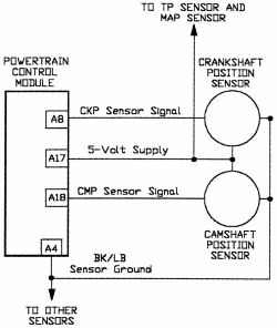
Camshaft Position Sensor
AutoZone Repair Guide for Engine Performance and Emission Control Components and Systems, specifically focusing on the Camshaft Position Sensor.
The Camshaft Position Sensor (CMP) is a critical component in modern internal combustion engines, playing a vital role in the management of...
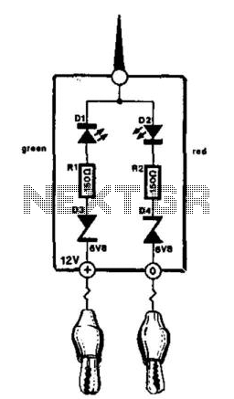
Automotive Electrical Tester
This compact tester is designed for checking vehicle electrical circuits. Two LEDs indicate whether one of the clips is connected to the positive supply line (red) or to ground (green). The unit is powered by the vehicle battery. It is...

Voltage Regulator For Cars And Motorcycles
This regulator circuit can be used on an alternator that has one field terminal grounded. When the input voltage becomes too high, Q1 conducts, and the base of Q2 is driven toward ground, reducing the voltage fed to Q3. This...
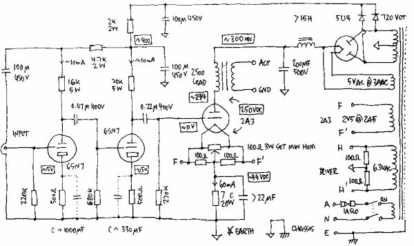
HOW TO READ CIRCUIT DIAGRAMS
This instructable will demonstrate how to interpret various circuit diagrams and assemble circuits on a breadboard.
The process of reading circuit diagrams involves understanding the symbols and connections that represent electronic components and their interrelations. Key components include resistors, capacitors, diodes,...