


why have my power dooe locks lost the power to operate correctly
#power surge
#door lock motors
#remote control
#central lock
#capacitor
#electrical issue
#vehicle electronics
#power drain
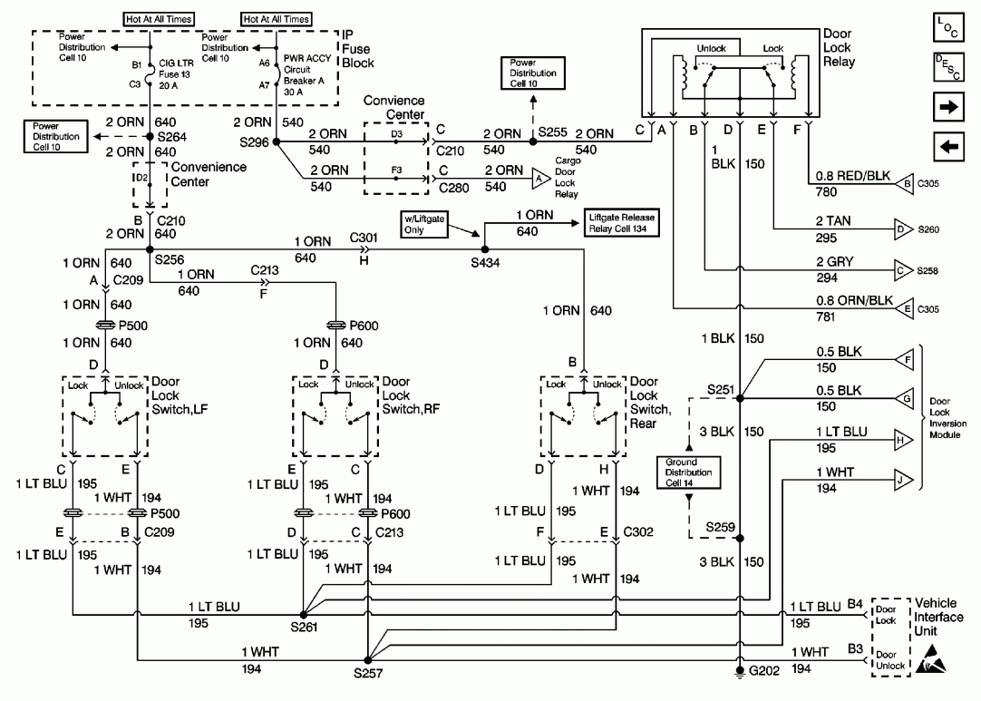
Description: The longer the locks remain unused with either the remote or central locking button, the stronger the power surge to the door lock motors. After being activated even once, it seems to drain all the power from the capacitor or whatever charge-storing component is present. After two or three attempts in a relatively short time, the motors become very fatigued. It is possible that one of the door actuator motors for the locks may be mechanically sticking. If any of them begin to fail to open or close properly in the near future, consideration should be given to replacing it or accessing the mechanism for lubrication. Regarding the fuse blowing, this may be acceptable, especially if the amplifier is active while the door locks are switched on or off multiple times. The locks are not intended for continuous use; they should only be operated in short bursts. In terms of the circuit, there are two primary components, in addition to the motors, that must function to supply power to the locks: the circuit breaker and the door lock relay. It is advisable to remove the circuit breaker from its socket to ensure the contacts are clean at both the socket and the breaker. This component is designed to open the circuit after prolonged use. The door lock relay is situated beneath the center of the instrument panel, near the remote control door lock receiver. It is also recommended to remove this relay and check the contacts of both the socket and the relay itself. A drawing of the locations of these components can be provided for clarity.
The door lock circuit operates by utilizing a series of components that ensure the efficient and safe functioning of the locking mechanism. The circuit breaker serves as a protective device that interrupts the electrical flow in case of overload, preventing damage to the system. The door lock relay acts as a switch that controls the power supplied to the door lock motors, allowing them to engage or disengage based on user input from the remote or central locking system.
To maintain optimal performance, regular inspection and maintenance of these components are essential. Cleaning the contacts of the circuit breaker and relay can significantly enhance the reliability of the locking system. If a door actuator motor is found to be sticking, it may lead to increased resistance in the system, resulting in higher power consumption and potential overheating. Lubrication of the mechanical components can alleviate this issue, ensuring smooth operation.
When troubleshooting the door locking mechanism, it is also important to consider the overall design of the circuit. The power supply to the locks should be managed carefully, with short bursts of operation to prevent overheating and subsequent fuse failure. If the system is subjected to frequent and prolonged use, it may lead to premature wear on the components, necessitating their replacement.
In summary, the door lock circuit consists of critical components that work together to provide secure and efficient locking. Proper maintenance and awareness of the operational limits can prolong the lifespan of the system and prevent common issues such as blown fuses or malfunctioning motors.The longer the locks are not used with either the remote or central lock button, the stronger the power surge to the door lock motors. After being "activated" even once, it is like it drains all the power out of the capacitor or whatever stores the charge if indeed this is the case.
two three attempts in a relatively short time and they become ver y tired. I am thinking that perhaps you have one of the door actuator motors (for the locks) that might be sticking (mechanically). So if you notice one of them starting to not open or close in the near future, you might want to think about replacing it, or getting to the mechanism and lubricating it.
As for the fuse blowing, that may actually be OK, especially if the amp is on at the same time the door locks are switched ON or OFF several times. The locks are not really supposed to be used like that, just in short bursts. On to the circuit. There are two main components (besides the motors) that need to be working to supply power to the locks.
They are the Circuit Breaker and the Door Lock Relay (see schematic below). What I would do is remove the circuit breaker from its socket and make sure the contacts are clean, at both the socket and the circuit breaker. This is designed to open the circuit after being used for a longer period of time (as mentioned above).
The Door Lock Relay is located under the center of the Instrument Panel, near the remote control door lock receiver. I would also remove it and check the contacts of both the socket and the relay itself. I will see if I can get you a drawing of where these parts are located. Ask-a-doc Web sites: If you`ve got a quick question, you can try to get an answer from sites that say they have various specialists on hand to give quick answers.
Justanswer. com. Traffic on JustAnswer rose 14 percent. and had nearly 400, 000 page views in 30 days. inquiries related to stress, high blood pressure, drinking and heart pain jumped 33 percent.
The door lock circuit operates by utilizing a series of components that ensure the efficient and safe functioning of the locking mechanism. The circuit breaker serves as a protective device that interrupts the electrical flow in case of overload, preventing damage to the system. The door lock relay acts as a switch that controls the power supplied to the door lock motors, allowing them to engage or disengage based on user input from the remote or central locking system.
To maintain optimal performance, regular inspection and maintenance of these components are essential. Cleaning the contacts of the circuit breaker and relay can significantly enhance the reliability of the locking system. If a door actuator motor is found to be sticking, it may lead to increased resistance in the system, resulting in higher power consumption and potential overheating. Lubrication of the mechanical components can alleviate this issue, ensuring smooth operation.
When troubleshooting the door locking mechanism, it is also important to consider the overall design of the circuit. The power supply to the locks should be managed carefully, with short bursts of operation to prevent overheating and subsequent fuse failure. If the system is subjected to frequent and prolonged use, it may lead to premature wear on the components, necessitating their replacement.
In summary, the door lock circuit consists of critical components that work together to provide secure and efficient locking. Proper maintenance and awareness of the operational limits can prolong the lifespan of the system and prevent common issues such as blown fuses or malfunctioning motors.The longer the locks are not used with either the remote or central lock button, the stronger the power surge to the door lock motors. After being "activated" even once, it is like it drains all the power out of the capacitor or whatever stores the charge if indeed this is the case.
two three attempts in a relatively short time and they become ver y tired. I am thinking that perhaps you have one of the door actuator motors (for the locks) that might be sticking (mechanically). So if you notice one of them starting to not open or close in the near future, you might want to think about replacing it, or getting to the mechanism and lubricating it.
As for the fuse blowing, that may actually be OK, especially if the amp is on at the same time the door locks are switched ON or OFF several times. The locks are not really supposed to be used like that, just in short bursts. On to the circuit. There are two main components (besides the motors) that need to be working to supply power to the locks.
They are the Circuit Breaker and the Door Lock Relay (see schematic below). What I would do is remove the circuit breaker from its socket and make sure the contacts are clean, at both the socket and the circuit breaker. This is designed to open the circuit after being used for a longer period of time (as mentioned above).
The Door Lock Relay is located under the center of the Instrument Panel, near the remote control door lock receiver. I would also remove it and check the contacts of both the socket and the relay itself. I will see if I can get you a drawing of where these parts are located. Ask-a-doc Web sites: If you`ve got a quick question, you can try to get an answer from sites that say they have various specialists on hand to give quick answers.
Justanswer. com. Traffic on JustAnswer rose 14 percent. and had nearly 400, 000 page views in 30 days. inquiries related to stress, high blood pressure, drinking and heart pain jumped 33 percent.
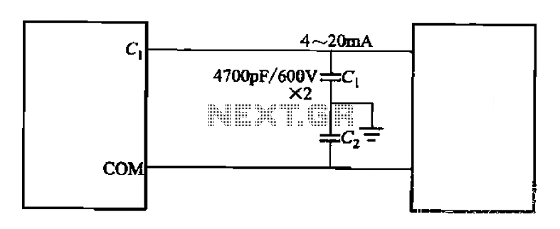
Control cables plus anti-interference capacitors
A capacitor filter is utilized in frequency control circuits and is a common method for implementing anti-jamming measures. It addresses frequency interference noise within the wiring of the 4-20mA control loop. The anti-interference is achieved through bypass capacitors C1 and...
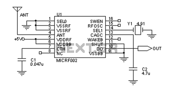
200 meters remote control schematic design
Early transmitters using LC oscillators experience significant frequency drift. The introduction of Surface Acoustic Wave (SAW) devices addresses this issue, providing substantial frequency stability comparable to crystals. These devices can achieve fundamental frequencies in the hundreds of megahertz or even...
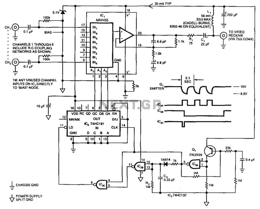
Remote-Controlled Switcher
This single-cable system transmits composite video (NTSC, PAL, or SECAM), power, and channel selection signals. The interface end of the circuit delivers 10 V down the cable, pulses the supply voltage to transmit channel-change commands, and buffers the received video...
Atari Joystick Wired Remote Control for Robots
The simplest solution for implementing joystick control for a robot is to program the actions in software on a microcontroller. However, many users prefer off-the-shelf components, thus this circuit is designed using diodes, resistors, transistors, and a FAN8200 motor driver...
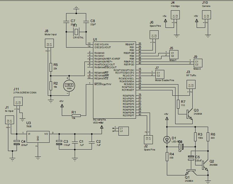
remote controlled surveillance mobile robot
The project is developed by Team Stark, with Gilbert as the leader and team members Martin and Janssen. The tasks have been divided into three parts. The first part includes camera control, login database, installer, and network setup, which was...
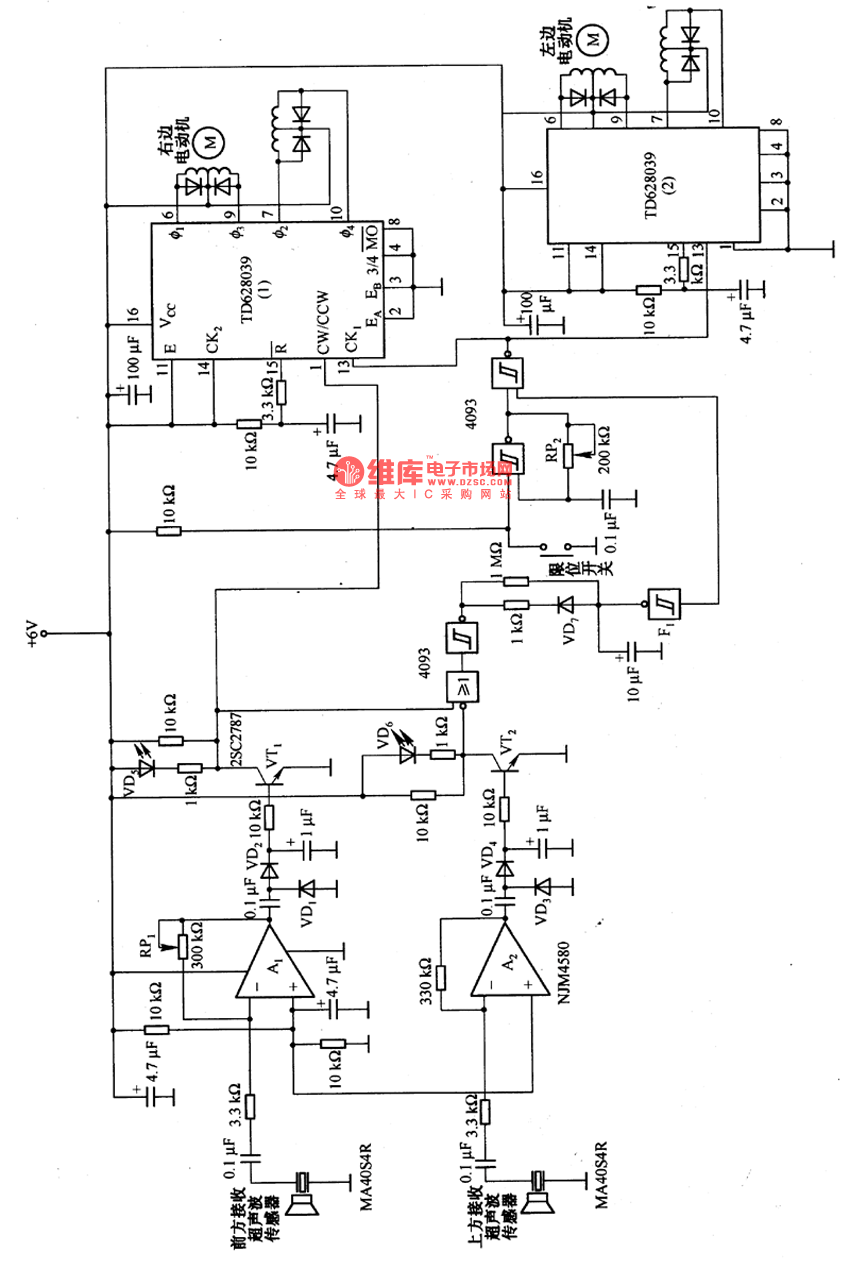
Remote control robot circuit
The remote control robot circuit is illustrated in the accompanying figure. Figure 2-36(a) presents the circuit diagram, while figure 2-36(b) depicts the operating timing diagram. The robot's rotation process involves an ultrasonic launching circuit, which consists of a 40 kHz...
Atari Joystick Wired Remote Control for Robots
The simplest solution for implementing joystick control for a robot is to program the actions in software on a microcontroller. However, many users prefer off-the-shelf components, thus this circuit is designed using diodes, resistors, transistors, and a FAN8200 motor driver...
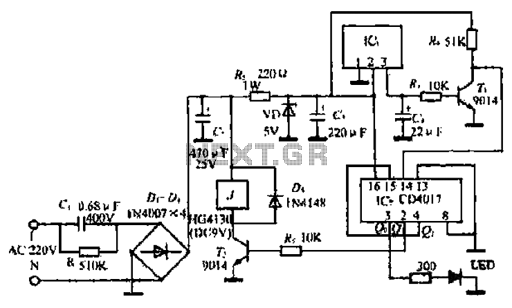
A simple remote control switch circuit
The ML4423 is an integrated controller designed for single-phase and two-phase AC induction motors. It features PWM (Pulse Width Modulation) capabilities for speed control and includes various protection circuits such as short circuit protection, fire protection, and a reference power...
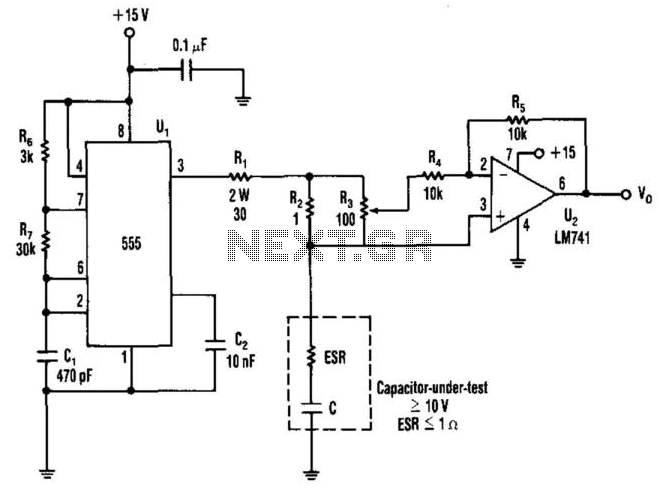
Capacitor Esr Measurer
The equivalent series resistance (ESR) of a capacitor can be measured using this circuit and an AC voltmeter. It functions as a 50-kHz square-wave generator, driving a current waveform of approximately ±180 mA through the capacitor-under-test via resistors R1 and...