


6V Gel Cell Battery Charger
#gel cell battery
#regulated power supply
#trickle charge
#NPN transistor
#TO-220 case
#ceramic capacitors
#automatic switching
#10V-DC
#2 Amps
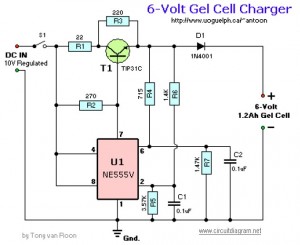
Description: This circuit requires a regulated 10V DC front end capable of supplying 2 Amps. It begins the charging period at 240mA and automatically switches to a float condition (trickle charge) of 12mA when fully charged. The capacitors should be ceramic models rated for 50V or greater. The switching transistor T1 is an NPN Si-Power Output/SW type with a TO-220 case and can be substituted with appropriate alternatives such as the NTE291 or ECG291. The timer/oscillator U1 is an 8-pin NE555V, which can be replaced with an NTE955M or ECG955M. Resistors R4, R5, R6, and R7 are 1% metal film types, which may not be available at local retailers like Radio Shack/Tandy and should be ordered from suppliers such as Electro-Sonic or Newark Electronics.
This circuit is designed as a 6V Gel Cell Charger, suitable for charging gel cell batteries. It is important to ensure that the charging voltage does not exceed the voltage generated by the solar panel when used in a solar-powered application. The charger is regulated and adjustable, making it compatible with various NiCAD battery configurations, whether single cells or multi-cell arrangements connected in series or parallel. The maximum allowable voltage for the batteries is 18V.
Power transistors Q1 and Q2 function as series regulators, ensuring stable output during the charging process. The circuit also includes an automatic 9V battery charger design, initially developed by Jan Hamer and translated by Tony Van Roon, adhering to European standards. Resistor values in the schematic are specified in ohms, with examples including 120E and 150E.
Additionally, a lead-acid battery charger circuit is included, providing an initial voltage of 2.5V per cell at 25°C to facilitate rapid charging. As the battery charges, the current decreases, and when it drops to 180mA, the charging circuit reduces the output voltage accordingly.
For rechargeable lithium batteries, a charging circuit is designed to deliver a constant current of 60mA for AA cells, with a cutoff voltage of 2.4V per cell to terminate the charge. This system is suitable for multi-cell battery packs consisting of 2 to 6 series-connected cells.
Lastly, the schematic for a 12V NiCAD battery charger is provided, which operates at a charging rate of 200mA per hour. This charger initially delivers 75mA until the battery reaches full charge, after which it switches to a trickle charge to maintain battery health. The circuit is capable of fully recharging a completely depleted battery in approximately 4 hours.This circuit requires a regulated 10V-DC front end capable of supplying 2 Amps. Begins the charge period at 240mA and at full charge switches automatically to a float condition (trickle charge) of 12mA. The capacitors should be the ceramic 50V (or greater) model. Switching transistor T1 is an NPN, Si-Power Output/SW, with a TO-220 case and can be changed by using a appropriate substitute such as the NTE291, ECG291, etc. Timer/Oscillator U1 is a 8-pin NE555V and can be changed with a NTE955M or ECG955M. Resistors R4, R5, R6, and R7 are 1% metal film types. They may not be obtainable at your nearby Radio Shack/Tandy retailer and need to be ordered in. Try Electro-Sonic or Newark Electronics supply stores. Tags: 6V Gel Cell Charger circuit, 6V Gel Cell Charger diagram, Gel Cell Battery, Gel Cell Battery Charger, Gel Cell Battery Charger circuit, Gel Cell Battery Charger schematic, Gel Cell Charger, Gel Cell charger circuit, Gel Cell charger diagram, Gel Cell charger schematic, This is the schematic diagram of solar powered mobile phone battery charger. The circuit is designed to charge the battery from a source with a lower voltage. Do not use it to charge the battery with the same or lower voltage than the voltage which is generated by the solar panel.
For proper operation of. This battery charger circuit is regulated and adjustable to make this circuit able to charge the mosto NiCAD battery. This circuit will work for single cell or multi battery cell which connected with series/parallel connection.
The maximum voltage of the batteries should be 18V maximum. Power transistors Q1 and Q2 are connected as series regulators. This is the diagram of Automatic 9V Battery Charger circuit. The circuit designed by Jan Hamer, translated by Tony Van Roon dan republished in this circuit diagram site. The circuit details are based on european standards. 120E, 150E, etc. The `E` just stands for Ohms so 120 ohm, 150 ohm. The original circuit specified the. The following diagram is the circuit diagram of Lead-Acid battery charger. This circuit provides an initial voltage of 2. 5 V per cell at 25 ƒ to quickly charge the battery. The charging current decreases as the battery is charging, and when the current drops to 180 mA, the charging circuit reduces the output voltage of.
This battery charger circuit is used for rechargable lithium battery. Charging is accomplished with a constant current of 60 mA for AA cells to a cutoff of 2. 4V per cell, at which point the charge must be terminated. The charging system shown is designed for multi-cell battery pack of 2 to 6 series connected cell. The following diagram is the schematic diagram of 12V NiCAD battery charger with charging rate of 200mA/Hour. This NiCAD battery charger circuit charges the battery at 75 mA until the battery is charged, then it reduces the current to a trickle rate.
It will fully recharge a dead/unpowered battery in 4 hours and the battery.
This circuit is designed as a 6V Gel Cell Charger, suitable for charging gel cell batteries. It is important to ensure that the charging voltage does not exceed the voltage generated by the solar panel when used in a solar-powered application. The charger is regulated and adjustable, making it compatible with various NiCAD battery configurations, whether single cells or multi-cell arrangements connected in series or parallel. The maximum allowable voltage for the batteries is 18V.
Power transistors Q1 and Q2 function as series regulators, ensuring stable output during the charging process. The circuit also includes an automatic 9V battery charger design, initially developed by Jan Hamer and translated by Tony Van Roon, adhering to European standards. Resistor values in the schematic are specified in ohms, with examples including 120E and 150E.
Additionally, a lead-acid battery charger circuit is included, providing an initial voltage of 2.5V per cell at 25°C to facilitate rapid charging. As the battery charges, the current decreases, and when it drops to 180mA, the charging circuit reduces the output voltage accordingly.
For rechargeable lithium batteries, a charging circuit is designed to deliver a constant current of 60mA for AA cells, with a cutoff voltage of 2.4V per cell to terminate the charge. This system is suitable for multi-cell battery packs consisting of 2 to 6 series-connected cells.
Lastly, the schematic for a 12V NiCAD battery charger is provided, which operates at a charging rate of 200mA per hour. This charger initially delivers 75mA until the battery reaches full charge, after which it switches to a trickle charge to maintain battery health. The circuit is capable of fully recharging a completely depleted battery in approximately 4 hours.This circuit requires a regulated 10V-DC front end capable of supplying 2 Amps. Begins the charge period at 240mA and at full charge switches automatically to a float condition (trickle charge) of 12mA. The capacitors should be the ceramic 50V (or greater) model. Switching transistor T1 is an NPN, Si-Power Output/SW, with a TO-220 case and can be changed by using a appropriate substitute such as the NTE291, ECG291, etc. Timer/Oscillator U1 is a 8-pin NE555V and can be changed with a NTE955M or ECG955M. Resistors R4, R5, R6, and R7 are 1% metal film types. They may not be obtainable at your nearby Radio Shack/Tandy retailer and need to be ordered in. Try Electro-Sonic or Newark Electronics supply stores. Tags: 6V Gel Cell Charger circuit, 6V Gel Cell Charger diagram, Gel Cell Battery, Gel Cell Battery Charger, Gel Cell Battery Charger circuit, Gel Cell Battery Charger schematic, Gel Cell Charger, Gel Cell charger circuit, Gel Cell charger diagram, Gel Cell charger schematic, This is the schematic diagram of solar powered mobile phone battery charger. The circuit is designed to charge the battery from a source with a lower voltage. Do not use it to charge the battery with the same or lower voltage than the voltage which is generated by the solar panel.
For proper operation of. This battery charger circuit is regulated and adjustable to make this circuit able to charge the mosto NiCAD battery. This circuit will work for single cell or multi battery cell which connected with series/parallel connection.
The maximum voltage of the batteries should be 18V maximum. Power transistors Q1 and Q2 are connected as series regulators. This is the diagram of Automatic 9V Battery Charger circuit. The circuit designed by Jan Hamer, translated by Tony Van Roon dan republished in this circuit diagram site. The circuit details are based on european standards. 120E, 150E, etc. The `E` just stands for Ohms so 120 ohm, 150 ohm. The original circuit specified the. The following diagram is the circuit diagram of Lead-Acid battery charger. This circuit provides an initial voltage of 2. 5 V per cell at 25 ƒ to quickly charge the battery. The charging current decreases as the battery is charging, and when the current drops to 180 mA, the charging circuit reduces the output voltage of.
This battery charger circuit is used for rechargable lithium battery. Charging is accomplished with a constant current of 60 mA for AA cells to a cutoff of 2. 4V per cell, at which point the charge must be terminated. The charging system shown is designed for multi-cell battery pack of 2 to 6 series connected cell. The following diagram is the schematic diagram of 12V NiCAD battery charger with charging rate of 200mA/Hour. This NiCAD battery charger circuit charges the battery at 75 mA until the battery is charged, then it reduces the current to a trickle rate.
It will fully recharge a dead/unpowered battery in 4 hours and the battery.
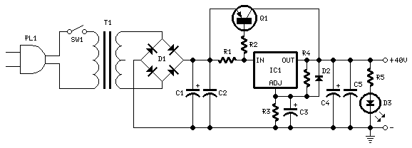
40v regulated power supply based tip42a and lm317
40V regulated power supply based on TIP42A and LM317. Refer to the specified page for an explanation of the related circuit diagram.
The 40V regulated power supply utilizes a TIP42A transistor and an LM317 voltage regulator to provide a stable output...
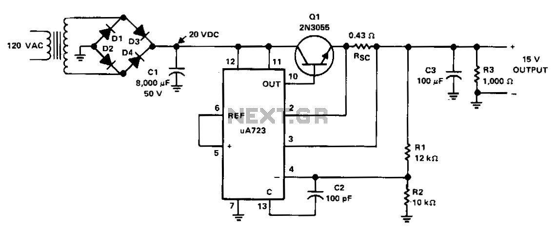
+15-V-1-a-regulated-power-supply
The power supply receives +20 VDC from the rectifier/filter section. This voltage is applied to pins 11 and 12 of the uA723 voltage regulator, as well as to the collector of the 2N3055 series-pass transistor. The output voltage is sampled...
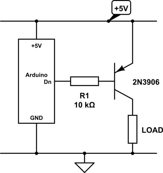
Is it possible to use an NPN transistor to control a 5V power supply from Arduino
The emitter will consistently be a few hundred millivolts lower than the base voltage in this configuration. With the base voltage set at 5V, the emitter voltage is likely to be around 4.5V, depending on the current drawn by the...
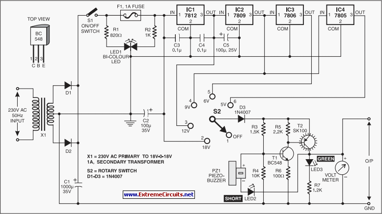
Stablised Power Supply With Short-Circuit Indication
This is an efficient four-stage stabilized power supply unit designed for testing electronic circuits. It delivers well-regulated and stabilized outputs, which are crucial for achieving accurate results in most electronic applications. The circuit features an audio-visual indication system that alerts...
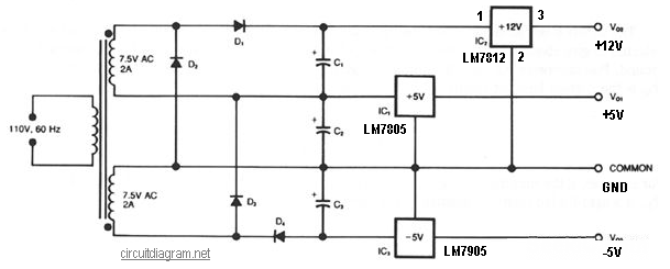
three rails regulated power supply
This circuit generates three source-regulated voltages using a minimal number of electronic components. The output DC voltages are +12V, +5V, and -5V. Diodes D2 and D3 perform full-wave rectification while charging capacitor C2 during each half of the alternating current...

Regulated 12 Volt Supply
This circuit above uses a 13 volt zener diode, D2 which provides the voltage regulation. Approximately 0.7 Volts are dropped across the transistors b-e junction, leaving a higher current 12.3 Volt output supply. This circuit can supply loads of up...
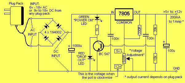
5-12V 200mA Regulated Power supply
It will accept AC from 6v to 18v or DC from 9v to 18v and any current up to 1 amp. The diode bridge on the input converts AC to DC and it doesn't matter which way around the leads...
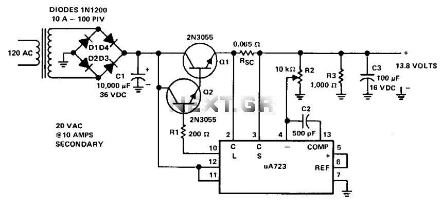
8-Amp regulated power supply
This power supply is powered by a transformer that operates from 120 Vac on the primary side and provides approximately 20 Vac on the secondary side. A full-wave bridge rectifier is constructed using four 10-A diodes rated at 100 PIV....
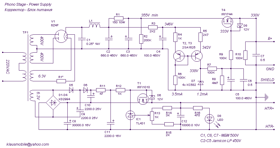
power supply (300V, 50mA + 6.3V, 3A max)
This regulated power supply was built as a simplified outboard version of a PSU in my first phono stage. Replacing hexfreds with tube rectifier eliminates the need for power-on sequencing. Chassis (salvaged from a hospital laser PSU) size is 180W*240D*100H...