


Accu charger use a diac and triac Schematic Diagram
#diac
#triac
#battery charger
#stable output
#fast charging
#gate circuit
#threshold level
#Accu
#cells battery
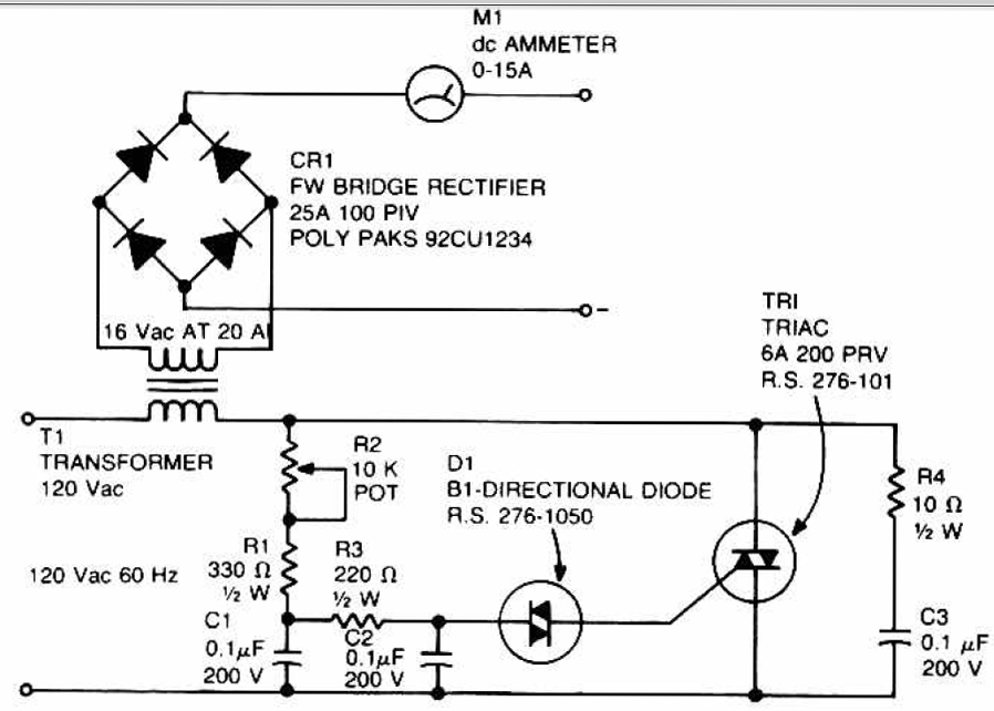
Description: This circuit can be used to charge accumulator and cell batteries. It features a very stable output that extends the battery life and maximizes the added battery capacity. The charging process is also quite fast, optimizing the time required for charging. A diac is employed in the gate circuit to establish a threshold level for firing the triac. Capacitor C3 and resistor R4 form a transient suppression network. Resistors R1, R2, and R3, along with capacitors C1 and C2, create a phase-shift network for the signal applied to the gate. Resistor R1 is selected to limit the maximum charging current when R2 is fully rotated.
The described circuit serves as an efficient battery charger for accumulator and cell batteries, utilizing a diac and triac configuration to enhance performance. The stability of the output voltage is crucial for prolonging battery life, as it prevents overcharging and ensures that the battery is charged within its optimal voltage range. The use of a diac in the gate circuit provides precise control over when the triac is triggered, ensuring that the charging process is initiated only when the input voltage exceeds a specific threshold. This mechanism helps to prevent potential damage to the battery from excessive current.
The transient suppression network, consisting of capacitor C3 and resistor R4, is essential for protecting the circuit from voltage spikes that could arise during the charging process. This network absorbs sudden changes in voltage, thereby safeguarding both the charger and the battery from potential harm.
The phase-shift network formed by resistors R1, R2, R3, and capacitors C1 and C2 plays a critical role in shaping the signal that is applied to the gate of the triac. This network is designed to ensure that the triac operates efficiently, allowing for smooth control of the charging current. Specifically, resistor R1 limits the maximum charging current when the adjustment potentiometer R2 is at its maximum setting, which is vital for preventing overheating and ensuring safe operation during the charging cycle.
Overall, this circuit design emphasizes stability, safety, and efficiency, making it an effective solution for charging accumulator and cell batteries.This circuit can be used to charge Accu and cells battery, the circuit can has a very stable output that would make the battery last longer and maximize the added battery capacity. When charge was also quite fast, so it can optimize the time. A diac is used in the gate circuit to provide a threshold level for firing the triac. C3 and R4 provide a transient suppression network. R1, R2, R3, C1, and C2 provide a hase - shift network for the signal being applied to the gate. R1 is selected to limit the maximum charging current at full rotation of R2. You are reading the Circuits of Accu charger use a diac and triac And this circuit permalink url it is
The described circuit serves as an efficient battery charger for accumulator and cell batteries, utilizing a diac and triac configuration to enhance performance. The stability of the output voltage is crucial for prolonging battery life, as it prevents overcharging and ensures that the battery is charged within its optimal voltage range. The use of a diac in the gate circuit provides precise control over when the triac is triggered, ensuring that the charging process is initiated only when the input voltage exceeds a specific threshold. This mechanism helps to prevent potential damage to the battery from excessive current.
The transient suppression network, consisting of capacitor C3 and resistor R4, is essential for protecting the circuit from voltage spikes that could arise during the charging process. This network absorbs sudden changes in voltage, thereby safeguarding both the charger and the battery from potential harm.
The phase-shift network formed by resistors R1, R2, R3, and capacitors C1 and C2 plays a critical role in shaping the signal that is applied to the gate of the triac. This network is designed to ensure that the triac operates efficiently, allowing for smooth control of the charging current. Specifically, resistor R1 limits the maximum charging current when the adjustment potentiometer R2 is at its maximum setting, which is vital for preventing overheating and ensuring safe operation during the charging cycle.
Overall, this circuit design emphasizes stability, safety, and efficiency, making it an effective solution for charging accumulator and cell batteries.This circuit can be used to charge Accu and cells battery, the circuit can has a very stable output that would make the battery last longer and maximize the added battery capacity. When charge was also quite fast, so it can optimize the time. A diac is used in the gate circuit to provide a threshold level for firing the triac. C3 and R4 provide a transient suppression network. R1, R2, R3, C1, and C2 provide a hase - shift network for the signal being applied to the gate. R1 is selected to limit the maximum charging current at full rotation of R2. You are reading the Circuits of Accu charger use a diac and triac And this circuit permalink url it is
ES-150
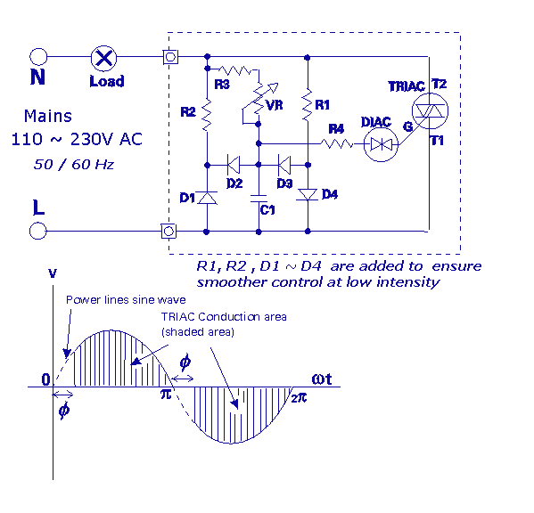
A light dimmer that utilizes a TRIAC and DIAC to control the brightness of light bulbs. It is based on a standard dimmer circuit, with several additional components included to eliminate flickering at low light levels. This design performs better...
TRIAC dimmer light circuit with dual time constant
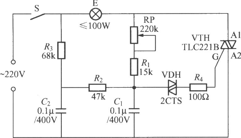
To address the lag and light transition issues, a Triac dimming light circuit featuring a dual time constant can be employed. This circuit enhances the resistor-capacitor network formed by R3 and C2. The reduced charge on capacitor C1 can be...
High Power AC Light Dimmer
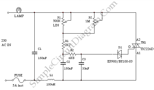
This is a light dimmer circuit. It does not include any special features and is a typical TRIAC-based dimmer circuit. This circuit is designed to operate with...
A TRIAC-based light dimmer circuit is a common electronic design used to control the...
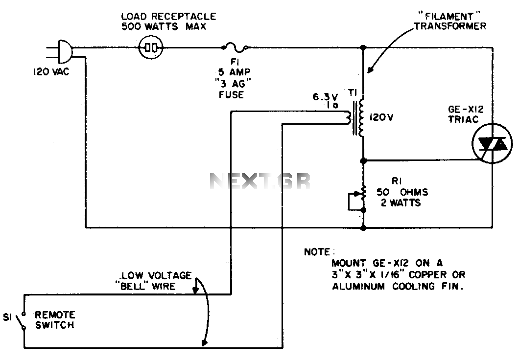
Remote control for lamp or appliance
The circuit utilizes the primary current of a small 6-volt filament transformer to control a triac and activate the load. When switch S1 in the 6-volt secondary of the transformer is open, a small "magnetizing" current flows through the primary...
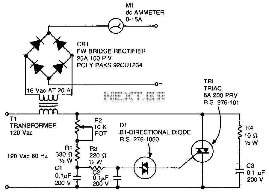
Battery charger
A diac is utilized in the gate circuit to enable operation for the signal applied to the gate. R1 sets a threshold level for triggering the triac. C3 and R4 are chosen to restrict the maximum charging current, forming a...
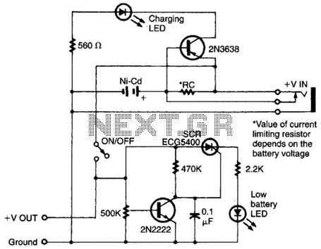
Intelligent Battery-Charging Circuit Circuit
Intended for a NiCad application, this charging circuit can be used with a wide range of batteries. A low-battery detector is included, and the trip voltage is set via a 500 kΩ potentiometer. Select the resistor for the battery you...
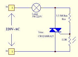
triac light switch circuit
The series of light switches is slightly different from traditional designs. These light switches can operate directly on the AC power network. The main components of the circuit include a TRIAC and a Light Dependent Resistor (LDR). The circuit is...
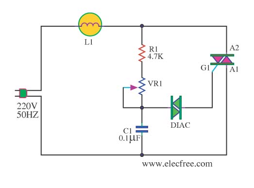
AC lights dimmer with triac
This circuit is designed to dim a light bulb with a maximum power rating of 100W. If the triac experiences high temperatures, it is essential to use a heat sink or allow for adequate heat dissipation. The diac functions as...
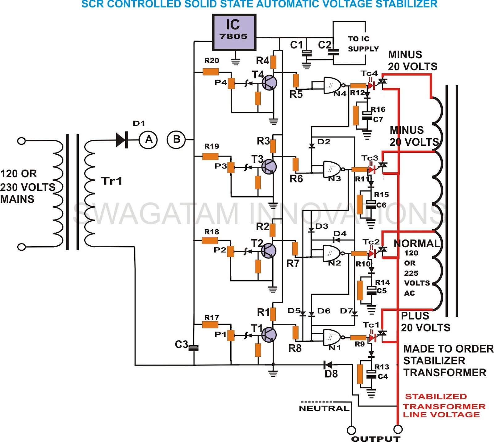
build solid state scrtriac controlled
This unique and hard-to-find triac-controlled AC voltage stabilizer circuit has been specifically designed for efficient voltage stabilization. With a solid-state design, the voltage switching transitions are smooth, resulting in minimal wear and tear. The proposed circuit provides four-step voltage stabilization...