


Arduino Runing On && Charging NiMH batteries
#arduino
#NiMH batteries
#voltage boost
#rechargeable batteries
#battery charging
#power management
#AA batteries
#energy efficiency
#circuit design
#embedded systems
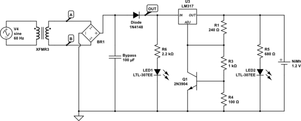
Description: An Arduino powered by 2 or 4 rechargeable NiMH AA batteries is being developed. The choice of using two batteries is based on the intention to boost the voltage to meet the requirements. The main challenge is ensuring that the batteries can charge while the project is plugged in. Each battery will have a capacity of approximately 2000-2400 mAh. Despite conducting extensive research on this topic, uncertainty remains regarding the next steps. It is understood that maintaining a constant current is crucial, with a trickle charge of less than 0.1C for NiMH batteries and a fast charge around 1.2C to 2C. The inquiry includes the possibility of creating a simple charger using an external 12V power supply, with the Arduino monitoring the battery voltage and shutting off the charge as necessary. The specific point in the circuit for voltage reading is of particular interest, as it is desired to know if the Arduino can read the battery voltage while the batteries are being charged. Additionally, there is consideration of using an integrated circuit (IC) to manage the charging process, and clarification is sought on whether the selected IC is suitable for this application.
An Arduino-based project utilizing 2 or 4 rechargeable NiMH AA batteries requires careful consideration of the charging mechanism to ensure efficient operation while allowing the batteries to charge when the system is connected to an external power supply. The chosen batteries, with a capacity of 2000-2400 mAh, necessitate a charging strategy that adheres to the recommended charging rates for NiMH technology, specifically a trickle charge of less than 0.1C and a fast charge of approximately 1.2C to 2C.
To create a simple charging circuit, an external 12V power supply can be used in conjunction with the Arduino. The Arduino can be programmed to monitor the battery voltage via an analog input pin. This voltage can be read at the battery terminals or at the output of the charging circuit, ensuring that the Arduino is capable of accurately assessing the battery's state of charge. Implementing a voltage divider may be necessary to bring the battery voltage within the Arduino's safe operating range, allowing for precise voltage readings.
In terms of managing the charging process, utilizing an integrated circuit designed for battery management could simplify the design and enhance safety. Such an IC would typically handle the charging current, provide temperature monitoring, and include features to prevent overcharging. It is essential to select an IC that is compatible with NiMH batteries and is capable of managing the desired charging rates. The circuit design should include bypass capacitors near the IC to ensure stable operation and minimize noise.
As this project represents a complex circuit design, it is advisable to create a schematic that outlines all components, including the Arduino, the battery configuration, the external power supply, and the charging IC. This schematic will serve as a foundation for further development, allowing for adjustments based on testing and performance evaluations.An Arduino running on 2 or 4 rechargeable NiMH AA batteries. I say 2 because I might boost up the voltage to what`s needed. My problem is that this project will sometimes be plugged in and I would like the batteries to be able to charge during that time. These batteries will each have a capacity of around 2000-2400 mAh. I must have done half a days amount of research on this topic and although I feel much more informed I still don`t know how to proceed. Based on what I`ve read the most important thing is a constant current, with <. 1c trickle charge for NiMH batteries and ~2c 1. 2cSource linked below for a fast charge. First off, is there a way to make a crude `dumb` charger with say an external 12v power supply and the Arduino reading the battery voltage and shut off accordingly If so where should the voltage be read at along the circuit for it to properly read. I`d like to know that last bit the most, because regardless of what charging mechanism in the end is selected, I wish to know whether the Arduino can read the battery voltage while the batteries are plugged in.
Also, should I in the end use an IC like and let it take care of the entire situation. If so is the one I have selected a good one for this particular application I have tried to continue research and attempt to present a circuit. I will say this is the most complicated circuit I have attempted to design. Besides the couple dozen schematics I had looked at, I mostly used the following:
An Arduino-based project utilizing 2 or 4 rechargeable NiMH AA batteries requires careful consideration of the charging mechanism to ensure efficient operation while allowing the batteries to charge when the system is connected to an external power supply. The chosen batteries, with a capacity of 2000-2400 mAh, necessitate a charging strategy that adheres to the recommended charging rates for NiMH technology, specifically a trickle charge of less than 0.1C and a fast charge of approximately 1.2C to 2C.
To create a simple charging circuit, an external 12V power supply can be used in conjunction with the Arduino. The Arduino can be programmed to monitor the battery voltage via an analog input pin. This voltage can be read at the battery terminals or at the output of the charging circuit, ensuring that the Arduino is capable of accurately assessing the battery's state of charge. Implementing a voltage divider may be necessary to bring the battery voltage within the Arduino's safe operating range, allowing for precise voltage readings.
In terms of managing the charging process, utilizing an integrated circuit designed for battery management could simplify the design and enhance safety. Such an IC would typically handle the charging current, provide temperature monitoring, and include features to prevent overcharging. It is essential to select an IC that is compatible with NiMH batteries and is capable of managing the desired charging rates. The circuit design should include bypass capacitors near the IC to ensure stable operation and minimize noise.
As this project represents a complex circuit design, it is advisable to create a schematic that outlines all components, including the Arduino, the battery configuration, the external power supply, and the charging IC. This schematic will serve as a foundation for further development, allowing for adjustments based on testing and performance evaluations.An Arduino running on 2 or 4 rechargeable NiMH AA batteries. I say 2 because I might boost up the voltage to what`s needed. My problem is that this project will sometimes be plugged in and I would like the batteries to be able to charge during that time. These batteries will each have a capacity of around 2000-2400 mAh. I must have done half a days amount of research on this topic and although I feel much more informed I still don`t know how to proceed. Based on what I`ve read the most important thing is a constant current, with <. 1c trickle charge for NiMH batteries and ~2c 1. 2cSource linked below for a fast charge. First off, is there a way to make a crude `dumb` charger with say an external 12v power supply and the Arduino reading the battery voltage and shut off accordingly If so where should the voltage be read at along the circuit for it to properly read. I`d like to know that last bit the most, because regardless of what charging mechanism in the end is selected, I wish to know whether the Arduino can read the battery voltage while the batteries are plugged in.
Also, should I in the end use an IC like and let it take care of the entire situation. If so is the one I have selected a good one for this particular application I have tried to continue research and attempt to present a circuit. I will say this is the most complicated circuit I have attempted to design. Besides the couple dozen schematics I had looked at, I mostly used the following:
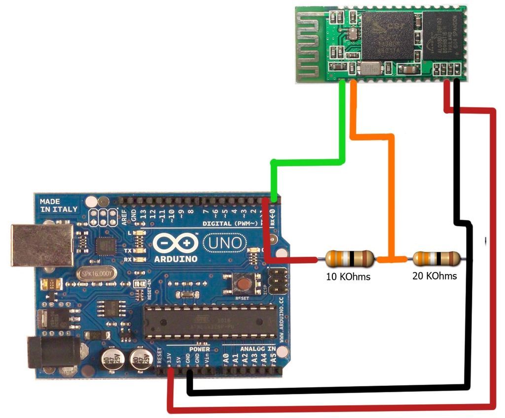
Hercules: The Motion Controlled Android Robot using Arduino
The motion games on the Nokia 5800 sparked an interest in creating a real-world version of a racing car controlled by tilting a phone. The motion-controlled robot, named Hercules due to its high torque and speed, is operated via Bluetooth...
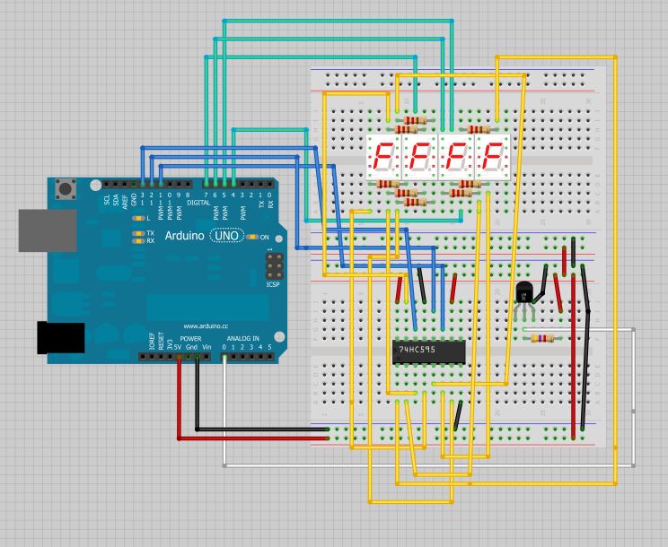
Temperature Displayed on 4 Digit 7 segment using Arduino
The intention is to utilize this code in future projects involving 7-segment displays. For those interested in learning more about 7-segment displays, additional information can be found in a related post.
7-segment displays are widely used in electronic devices for visual...
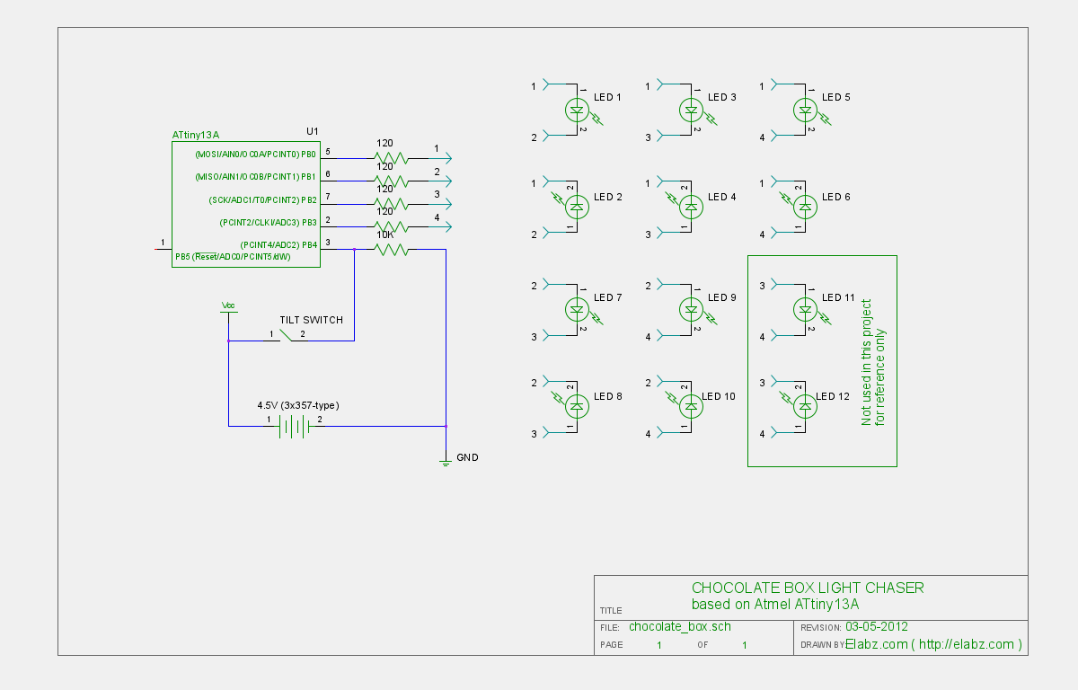
Pimp Your Chocolates with Arduino IDE and ATTiny13
Transform a standard chocolate box into an impressive LED blinking display using an ATTiny13 AVR microcontroller, Arduino IDE, and several electronic components.
The project involves creating an eye-catching LED display housed within a chocolate box. The core of the circuit is...
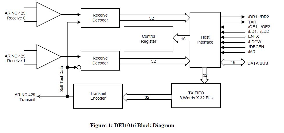
Interfacing Electronic Circuits to Arduinos
This document outlines the process of interfacing an Arduino with an ARINC 429 transceiver, illustrating the general methodology for connecting an Arduino to electronic circuits that can be applied to individual designs. The ARINC 429 bus is the predominant data...
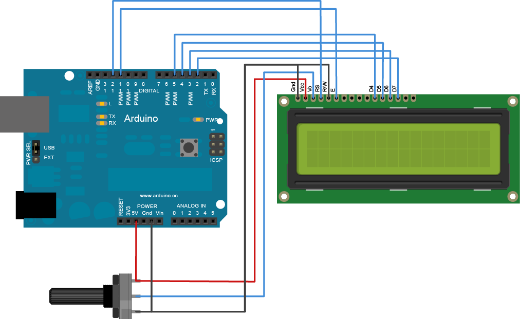
Arduino Liquid Crystal Cursor
The Liquid Crystal Library enables control of LCD displays compatible with the Hitachi HD44780 driver. Many such displays are available, typically identifiable by their 16-pin interface. It is advisable to solder a pin header strip to the 14 (or 16)...
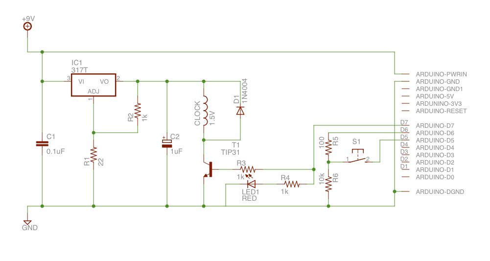
Make an Atom Synchronised Clock from a 1950s Slave Dial using Arduino
Upon purchasing the slave dial, it arrived without instructions, packaging, or additional details. The only visible markings, aside from decades of grime, were on the face (SMITH SECTRIC, ACELEC SYDNEY) and some markings on the bracket holding the mechanism (E....
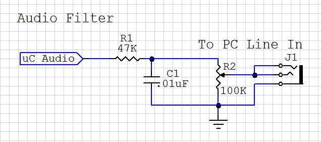
Arduino Audio DAC Options
DAC stands for Digital to Analog Converter. This article explores the code created by Michael Smith for a PWM-based DAC. The code has been modified to allow for the testing of various DAC options. A comparison is made between the...
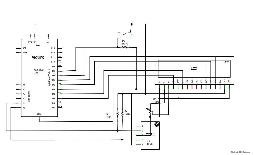
Arduino Liquid Crystal Displays
A tutorial on LCD communication was planned for a later date due to high demand. A circuit was already assembled for testing a new LCD provided by element14. The tutorial explains how communication functions with modern LCD character displays, showcasing...
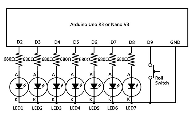
Arduino Make your own hardware
The Raspberry Pi single-board computer (SBC) has garnered significant attention for being a complete system priced under $50. However, it is not the most affordable computing device available. For only $13.50, a mini computer that connects to a PC's USB...