


Battery charger circuit using L200
#L200
#voltage regulator
#battery charger
#reverse polarity
#DC voltage
#charging circuit
#constant voltage
#rectifier
#IC
#electronics

Description: A simple battery charger circuit with reverse polarity indication is presented. The circuit utilizes the L200 integrated circuit, which is a five-pin variable voltage regulator. It can be powered by DC voltage from either a bridge rectifier or a center-tapped rectifier. The L200 maintains a constant charging voltage, while the charging current is regulated by the parallel combination of resistors R2 and R3. A potentiometer (P1) allows for adjustment of the charging current. This circuit is specifically designed to charge a 12V lead-acid battery. A transistor (T1), diode (D3), and LED are incorporated to create a reverse polarity indicator. If the battery is connected with reverse polarity, the red LED (D5) lights up. During the charging process, the green LED (D4) serves as the battery charging indicator.
The battery charger circuit described is a straightforward design aimed at efficiently charging a 12V lead-acid battery while providing visual feedback regarding the connection status of the battery. The L200 voltage regulator is the central component, functioning to deliver a stable output voltage suitable for charging. This integrated circuit is capable of handling input voltages higher than the output voltage, making it versatile for various power supply configurations.
The inclusion of a bridge rectifier or a center-tapped rectifier as the power source allows for flexibility in the circuit's application. The rectifier converts AC voltage to DC voltage, which is necessary for the operation of the L200. The output of the rectifier is connected to the input of the L200, ensuring that the voltage supplied to the battery remains consistent.
The charging current is controlled through the resistors R2 and R3, which are connected in parallel. The values of these resistors determine the maximum charging current that can flow to the battery. Additionally, the potentiometer P1 provides an adjustable means to fine-tune the charging current based on the specific requirements of the battery being charged. This feature is particularly useful for accommodating different battery conditions or types.
To enhance the safety and usability of the circuit, a reverse polarity indicator is integrated using a transistor (T1), a diode (D3), and an LED (D5). This configuration ensures that if the battery is connected incorrectly, the red LED will illuminate, alerting the user to the error. This prevents potential damage to the battery and the charging circuit itself.
Furthermore, during the normal charging process, the green LED (D4) serves as a charging indicator, providing visual confirmation that the battery is being charged correctly. This dual LED setup not only improves user experience but also enhances safety by clearly indicating the operational status of the charger.
Overall, this battery charger circuit is designed for simplicity and effectiveness, making it suitable for hobbyist applications and small-scale battery charging needs. Proper component selection and circuit design ensure reliable performance while maintaining user safety through visual indicators.A very simple battery charger circuit having reverse polarity indication is shown here. The circuit is based on IC L200. L200 is a five pin variable voltage voltage regulator IC. The charging circuit can be fed by the DC voltage from a bridge rectifier or center tapped rectifier. Here the IC L200 keeps the charging voltage constant. The charging curr ent is controlled by the parallel combination of the resistors R2 & R3. The POT P1 can be used to adjust the charging current. This circuit is designed to charge a 12 V lead acid battery. The transistor t1, diode D3 and LED are used to make a battery reverse indicator. In case the battery is connected in reverse polarity, the reverse polarity indicator red LED D5 glows. When the charging process is going on the battery charging indicator green LED D4 glows. We aim to transmit more information by carrying articles. Please send us an E-mail to wanghuali@hqew. net within 15 days if we are involved in the problems of article content, copyright or other problems.
We will delete it soon.
The battery charger circuit described is a straightforward design aimed at efficiently charging a 12V lead-acid battery while providing visual feedback regarding the connection status of the battery. The L200 voltage regulator is the central component, functioning to deliver a stable output voltage suitable for charging. This integrated circuit is capable of handling input voltages higher than the output voltage, making it versatile for various power supply configurations.
The inclusion of a bridge rectifier or a center-tapped rectifier as the power source allows for flexibility in the circuit's application. The rectifier converts AC voltage to DC voltage, which is necessary for the operation of the L200. The output of the rectifier is connected to the input of the L200, ensuring that the voltage supplied to the battery remains consistent.
The charging current is controlled through the resistors R2 and R3, which are connected in parallel. The values of these resistors determine the maximum charging current that can flow to the battery. Additionally, the potentiometer P1 provides an adjustable means to fine-tune the charging current based on the specific requirements of the battery being charged. This feature is particularly useful for accommodating different battery conditions or types.
To enhance the safety and usability of the circuit, a reverse polarity indicator is integrated using a transistor (T1), a diode (D3), and an LED (D5). This configuration ensures that if the battery is connected incorrectly, the red LED will illuminate, alerting the user to the error. This prevents potential damage to the battery and the charging circuit itself.
Furthermore, during the normal charging process, the green LED (D4) serves as a charging indicator, providing visual confirmation that the battery is being charged correctly. This dual LED setup not only improves user experience but also enhances safety by clearly indicating the operational status of the charger.
Overall, this battery charger circuit is designed for simplicity and effectiveness, making it suitable for hobbyist applications and small-scale battery charging needs. Proper component selection and circuit design ensure reliable performance while maintaining user safety through visual indicators.A very simple battery charger circuit having reverse polarity indication is shown here. The circuit is based on IC L200. L200 is a five pin variable voltage voltage regulator IC. The charging circuit can be fed by the DC voltage from a bridge rectifier or center tapped rectifier. Here the IC L200 keeps the charging voltage constant. The charging curr ent is controlled by the parallel combination of the resistors R2 & R3. The POT P1 can be used to adjust the charging current. This circuit is designed to charge a 12 V lead acid battery. The transistor t1, diode D3 and LED are used to make a battery reverse indicator. In case the battery is connected in reverse polarity, the reverse polarity indicator red LED D5 glows. When the charging process is going on the battery charging indicator green LED D4 glows. We aim to transmit more information by carrying articles. Please send us an E-mail to wanghuali@hqew. net within 15 days if we are involved in the problems of article content, copyright or other problems.
We will delete it soon.
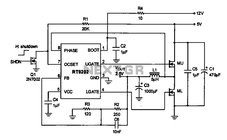
2.5V voltage regulator circuit
A 2.5V voltage regulator circuit is illustrated, which is part of a computer's motherboard. The circuit employs an oscillation circuit with the RT9202 control core chip, converting a 5V input supply into a regulated +2.5V output voltage, with the chip's...
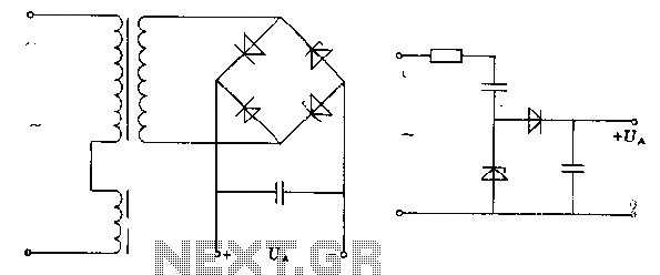
Zero rectifier regulator schematic
The pre-regulator circuit is connected to a capacitor and a resistor element. The regulator operates in its conducting direction through the input. A capacitor is connected to AC power, and in the blocking direction, it limits the current, allowing the...
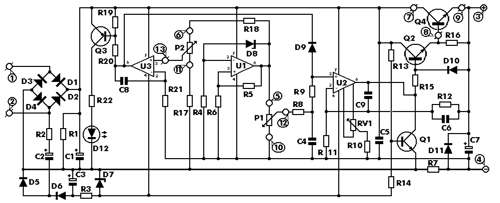
STABILIZER POWER SUPPLY 0-30 VDC CIRCUIT
This is an aerial current power supply with a continuously adjustable stabilized output ranging from 0 to 30VDC. The circuit also incorporates an electronic current limiter that effectively controls the output current from a few milliamperes (2 mA) to a...
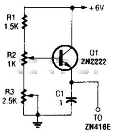
+1.5V Supply For Zn416E circuits
This regulator can be used with a +6-V source to supply the ZN416E low-voltage TRF radio receiver IC with the necessary +1.5 V. R3 sets the output voltage.
The circuit utilizes a voltage regulator designed to convert a +6 V input...
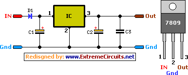
9 Volt 2 Ampere DC Power Supply Circuit
This circuit primarily relies on a voltage regulator. The 7809 voltage regulator can provide a continuous output of up to 2 amps while ensuring a low noise and highly regulated supply. Although the circuit can function without additional components, a...

12V DC Dual Power Supply Circuit with IC 7812&7912
The 78W series voltage regulators are designed to handle an input voltage of approximately 35V, while the 24V type can withstand up to 40V. It should be noted that these regulators will not operate effectively with a significant input-output voltage...
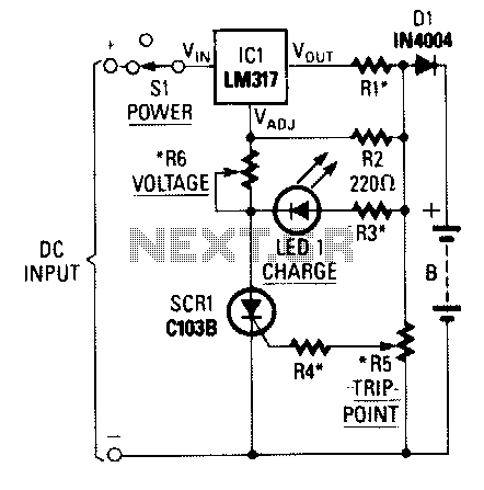
Universal-battery-charger
When power is applied to the circuit, SCR1 is off, resulting in no bias current path to ground; thus, LM317 operates as a current regulator. The LM317 is connected to the battery through steering diode D1, limiting resistor R1, and...
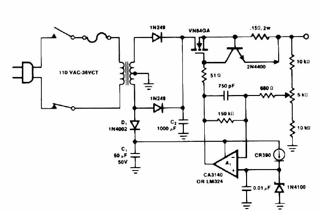
14 Volt Battery Charger Circuit Schematic Diagram
This circuit outputs a voltage of 14 volts with a maximum current of 4A. It can be used for NiCad batteries and accumulators, both wet and dry types. However, the accumulator must be rated for 12 volts and have a...
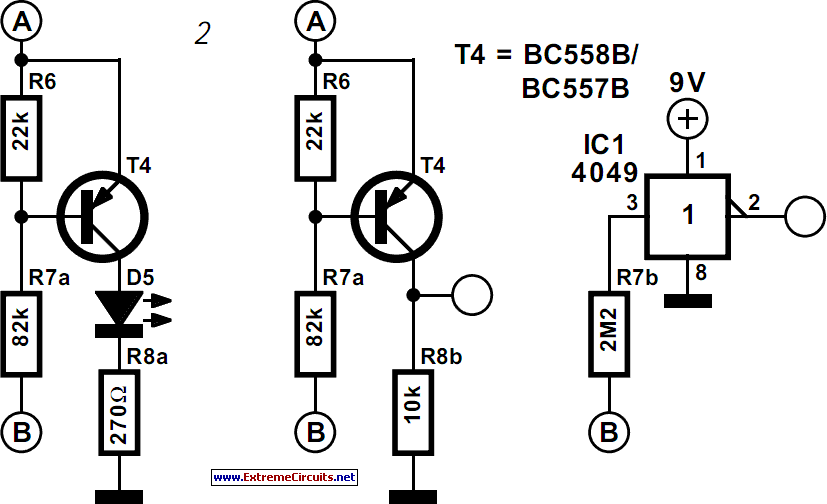
Thrifty Voltage Regulator
One of the drawbacks of a three-pin voltage regulator is that the input voltage needs to be 2.5 to 3 V higher than the output voltage. This makes these integrated regulators unsuitable for battery power supplies. For instance, if the...