


Electric shaver circuit
#electric shaver
#nickel-cadmium
#buck capacitor
#diode
#voltage regulation
#charging circuit
#portable device
#electronics
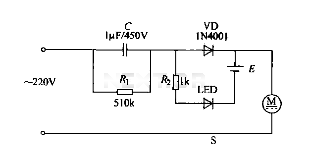
Description: The electric shaver circuit is illustrated in Figure 1-17. It features a buck capacitor (C) rated at 1 µF and 450V, which connects through diode VD to charge 1.2V nickel-cadmium batteries. Additionally, after the buck converter, there is a display element in the form of an LED. When the shaver is not in use, it is connected to a 220V power charger. To operate the device, a toggle switch (S) is used to turn on the motor, which drives the rotational movement of the shaver head.
The electric shaver circuit operates by utilizing a buck converter topology to efficiently step down the voltage from the power supply. The buck capacitor (C) plays a crucial role in smoothing out the voltage and ensuring stable operation of the circuit. The diode (VD) is essential for allowing current to flow in one direction, thereby preventing backflow that could damage the circuit components, particularly when charging the nickel-cadmium batteries.
The integration of an LED display serves as a visual indicator of the shaver's operational status, enhancing user interaction. The LED illuminates when the device is powered on, providing a clear signal that the shaver is ready for use. The toggle switch (S) enables the user to easily control the power to the motor, which is responsible for the rotational motion necessary for effective shaving.
When the shaver is not in operation, it remains connected to a 220V power source for charging. This design choice ensures that the nickel-cadmium batteries are continuously charged and ready for use, promoting convenience and ensuring the device is always operational when needed. The motor, upon activation, engages the shaver head, allowing for efficient hair removal through its rotational motion. The overall circuit design emphasizes safety, efficiency, and user-friendliness, making it suitable for everyday grooming needs.Electric shavers thorn circuit shown in Figure 1-17. Shown by the capacitance C buck, buck capacitor C is lyF/450V, pass through the diode VD, to 1.2V nickel-cadmium batteries. After Buck Island for the display element to the LED. When not in use, connected to the 220V power charger, so when used, toggle switch S, and the motor is turned on, the motor drives the shaver piece rotation.
The electric shaver circuit operates by utilizing a buck converter topology to efficiently step down the voltage from the power supply. The buck capacitor (C) plays a crucial role in smoothing out the voltage and ensuring stable operation of the circuit. The diode (VD) is essential for allowing current to flow in one direction, thereby preventing backflow that could damage the circuit components, particularly when charging the nickel-cadmium batteries.
The integration of an LED display serves as a visual indicator of the shaver's operational status, enhancing user interaction. The LED illuminates when the device is powered on, providing a clear signal that the shaver is ready for use. The toggle switch (S) enables the user to easily control the power to the motor, which is responsible for the rotational motion necessary for effective shaving.
When the shaver is not in operation, it remains connected to a 220V power source for charging. This design choice ensures that the nickel-cadmium batteries are continuously charged and ready for use, promoting convenience and ensuring the device is always operational when needed. The motor, upon activation, engages the shaver head, allowing for efficient hair removal through its rotational motion. The overall circuit design emphasizes safety, efficiency, and user-friendliness, making it suitable for everyday grooming needs.Electric shavers thorn circuit shown in Figure 1-17. Shown by the capacitance C buck, buck capacitor C is lyF/450V, pass through the diode VD, to 1.2V nickel-cadmium batteries. After Buck Island for the display element to the LED. When not in use, connected to the 220V power charger, so when used, toggle switch S, and the motor is turned on, the motor drives the shaver piece rotation.
Voltage Regulator
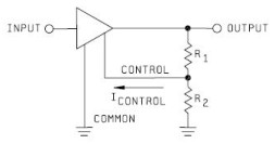
Neither term describes a regulator, only its placement within a circuit or system. Any voltage regulator could meet the requirements, depending on its placement. A listing of Analog Voltage Regulator IC manufacturers. The types of products or devices they produce...
Charging circuit diagram personal work
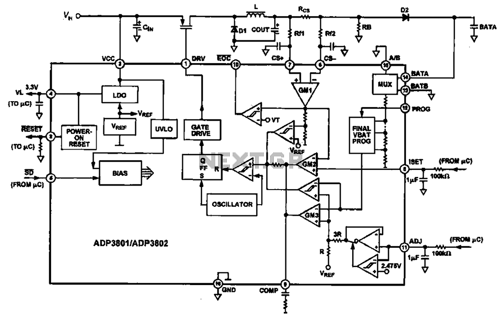
Charging circuit diagram for personal work based on the operating principle of ADP3801/3802 charging circuit.
The ADP3801/3802 is a highly integrated battery charger controller designed for Li-ion and Li-polymer batteries. The charging circuit typically consists of several key components including the...
Nickel-cadmium battery charger LM324 constituted
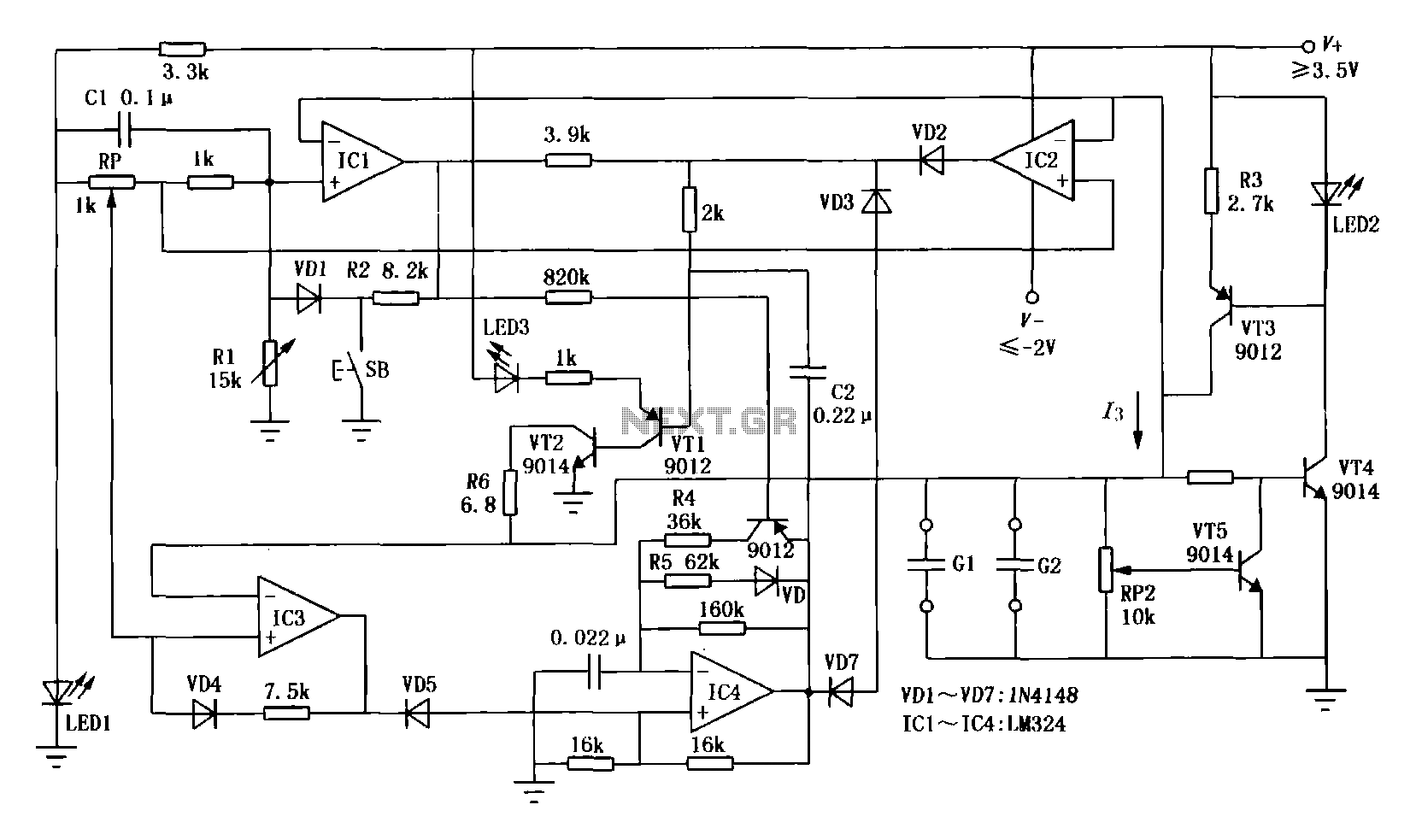
The first circuit is designed for discharging nickel-cadmium batteries before recharging to eliminate the "memory effect." After discharging, the power is automatically converted to the state of charge. The charging process utilizes pulse-width modulation for constant current, along with a...
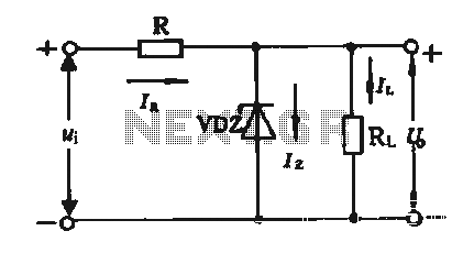
Regulator circuit silicon resistor formed
The simple voltage regulator circuit consists of a silicon regulator and a resistor. It is designed to rectify and filter DC voltage, as illustrated in the accompanying figure. The voltage regulator is connected in parallel with the load, and the...
Nickel-cadmium battery charger LM324 constituted
The first circuit is designed for discharging nickel-cadmium batteries before recharging to eliminate the "memory effect." After discharging, the power is automatically converted to the state of charge. The charging process utilizes pulse-width modulation for constant current, along with a...
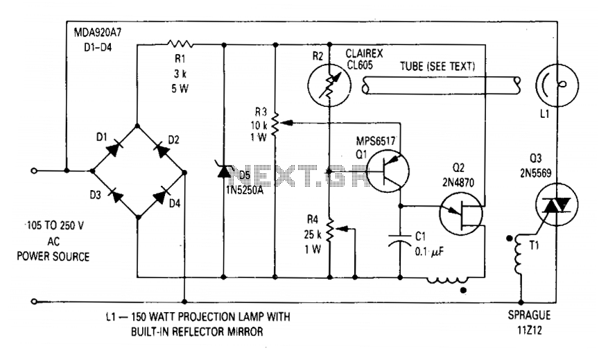
Voltage regulator for projection lamp
The circuit regulates the RMS output voltage across a load, specifically a projection lamp, to 100 volts ±2% for input voltages ranging from 105 to 250 volts AC. This regulation is achieved by indirectly sensing the light output of lamp...
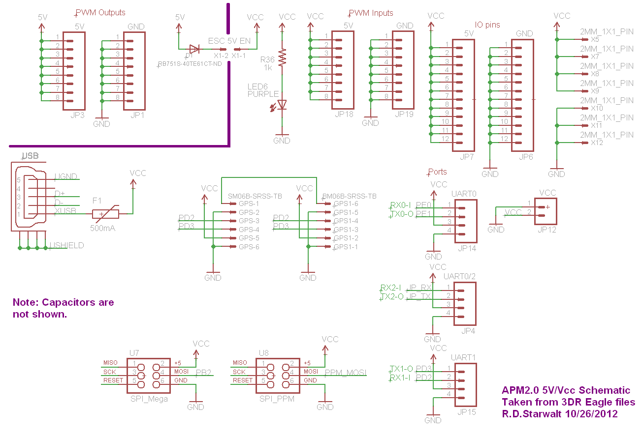
APM2.0 5V/Vcc Schematic
The PWM Output section has been separated into the upper left corner, delineated by a heavy purple line that is bridged by jumper JP1 on the APM2.0. This design choice highlights that diode D1 allows current to pass through JP1,...
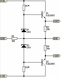
Simple Pre-Regulator
There will be many occasions when it is beneficial to utilize the P05 supply module sourced from a higher voltage supply. For instance, this could be advantageous when integrating balanced inputs.
The P05 supply module is designed to facilitate the conversion...
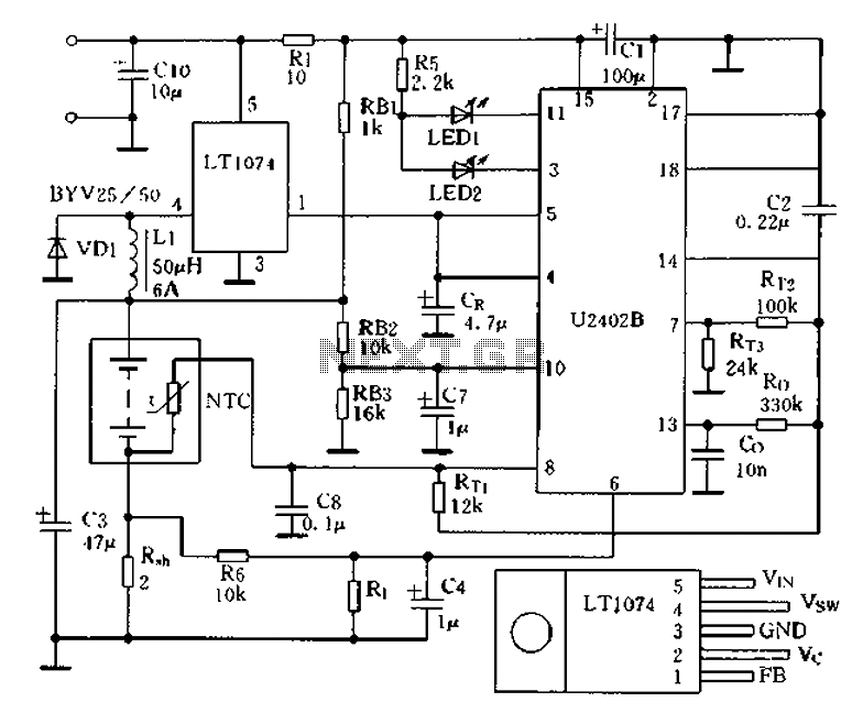
Charging circuit from the DC power supply switching power supply control
Charging circuit from the DC power supply switching power supply control
The charging circuit described is designed to operate with a DC power supply, utilizing a switching power supply control mechanism. This type of circuit is commonly employed in applications where...