


Intelligent pulse electric bicycle charger principle diagram
#TL494
#pulse width modulator
#voltage driving
#electric bicycle
#switching power circuit
#battery charging
#PWM
#power management
#voltage regulator
#energy
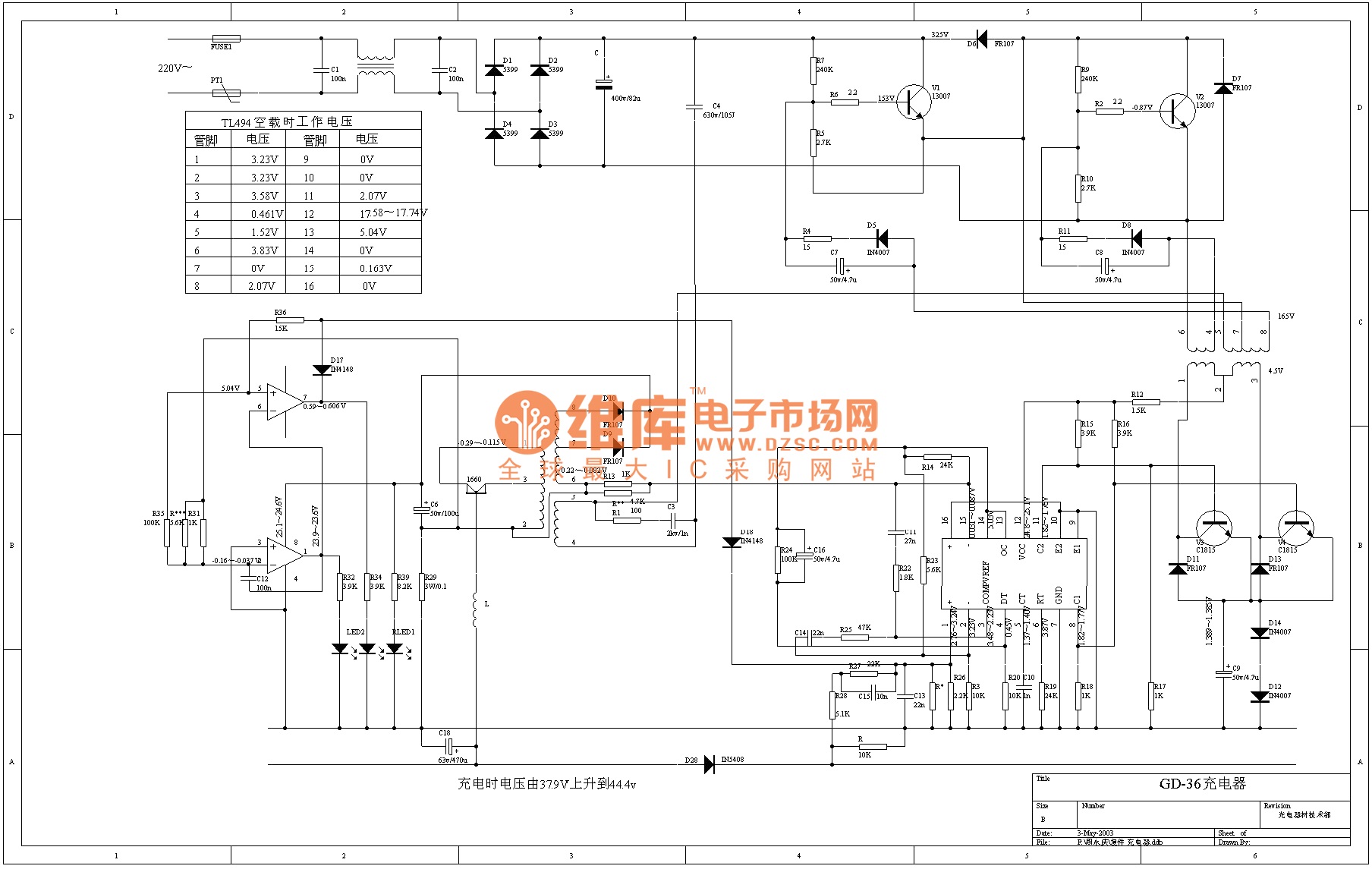
Description: The TL494 is a voltage-driven pulse width modulator produced by the United States company IR. It serves as a switching power circuit in various applications, including displays, computers, and other system circuits. The output transistor of the TL494 can be configured in either common emitter or emitter follower mode. This flexibility allows for the selection of either a push-pull output or a single-ended output mode. In push-pull mode, the two driving pulses are 180 degrees out of phase, whereas in single-ended mode, the two driving pulses share the same frequency and phase. The internal function diagram of the TL494 includes inputs such as 1IN+, 1IN-, 2IN+, feedback, DTC (non-load control), CT (timing capacitor), RT (timing resistor), GND (ground), collector outputs C1 and C2, emitter outputs E1 and E2, Vcc (power supply), OUTPUT CTR (output control), and REF (reference).
The TL494 pulse width modulator is designed for efficient power management and regulation in various electronic applications. Its dual output capability allows for versatile configuration options, making it suitable for both linear and switching power supply designs. The common emitter configuration is typically employed when higher output power is required, while the emitter follower configuration is advantageous for applications needing lower output impedance.
In practical applications, the TL494 can be used to regulate voltage and current in power supplies, providing stable output despite variations in input voltage or load conditions. The feedback mechanism incorporated within the device allows for real-time adjustments to maintain the desired output characteristics. The timing capacitor (CT) and timing resistor (RT) are critical components that determine the frequency and duty cycle of the output waveform, thus allowing for precise control over the power delivered to the load.
The TL494 is commonly utilized in applications such as DC-DC converters, battery chargers, and motor control circuits, where efficient power conversion and regulation are essential. By leveraging its internal features, designers can implement robust and reliable power management solutions that meet the demands of modern electronic systems.Voltage driving type pulse width modulator 1. feature and function of TL494 TL494 is produced by the United States IR company. It is voltage driving type pulse width modulator, which can be used as switching power circuit in display, computer and other system circuit. The output triode of TL494 can connect to the mode of common emitter or emitterfollower . So it can choose the double-end push-pull or single-end output mode. When ituses push-pull output mode, the differ of two drive pulse is 180 °, but when it is single end mode, its two ways ofdrive pulse have the same frequency and same phase. The internal function diagram of TL494 is shown in the following diagram 1IN+, 1IN-, 2IN+, 1IN input; FEEDBACK feed-back; DTC non load control; CT timing capacitor; RT timing resistor; GND ground; C1, C2 collector 1, 2; E1, E2 emitter 1, 2; Vcc power supply; OUTPUT CTR output control; REF reference.
2, application circuit
The TL494 pulse width modulator is designed for efficient power management and regulation in various electronic applications. Its dual output capability allows for versatile configuration options, making it suitable for both linear and switching power supply designs. The common emitter configuration is typically employed when higher output power is required, while the emitter follower configuration is advantageous for applications needing lower output impedance.
In practical applications, the TL494 can be used to regulate voltage and current in power supplies, providing stable output despite variations in input voltage or load conditions. The feedback mechanism incorporated within the device allows for real-time adjustments to maintain the desired output characteristics. The timing capacitor (CT) and timing resistor (RT) are critical components that determine the frequency and duty cycle of the output waveform, thus allowing for precise control over the power delivered to the load.
The TL494 is commonly utilized in applications such as DC-DC converters, battery chargers, and motor control circuits, where efficient power conversion and regulation are essential. By leveraging its internal features, designers can implement robust and reliable power management solutions that meet the demands of modern electronic systems.Voltage driving type pulse width modulator 1. feature and function of TL494 TL494 is produced by the United States IR company. It is voltage driving type pulse width modulator, which can be used as switching power circuit in display, computer and other system circuit. The output triode of TL494 can connect to the mode of common emitter or emitterfollower . So it can choose the double-end push-pull or single-end output mode. When ituses push-pull output mode, the differ of two drive pulse is 180 °, but when it is single end mode, its two ways ofdrive pulse have the same frequency and same phase. The internal function diagram of TL494 is shown in the following diagram 1IN+, 1IN-, 2IN+, 1IN input; FEEDBACK feed-back; DTC non load control; CT timing capacitor; RT timing resistor; GND ground; C1, C2 collector 1, 2; E1, E2 emitter 1, 2; Vcc power supply; OUTPUT CTR output control; REF reference.
2, application circuit
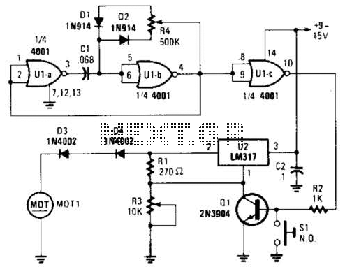
Pulse-Width-Modulated Motor-Speed Control Circuit
Connected in this manner, an LM317 1-A adjustable-voltage regulator can be utilized to control the speed of a miniature DC motor or to adjust the brightness of a small lamp. The circuit achieves this by modulating the pulse width, and...
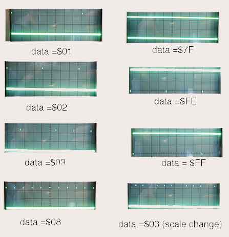
8 Channel PWM with AT90S1200
The assembly code given here was written to see what it would take to make an AT90S1200 generate 8 channels of proper PWM. In this case, by proper, I mean with the maximum high frequency content consistent with the needed...
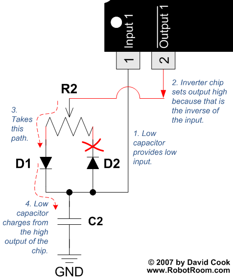
PWM - Pulse Width Modulation for DC Motor Speed and LED Brightness 2
To understand how the 74AC14 PWM circuit functions, it is essential to focus on the schematic section that includes the trimpot, diodes, capacitor, and the first inverter logic gate. Initially, when power is applied to the circuit, the capacitor is...
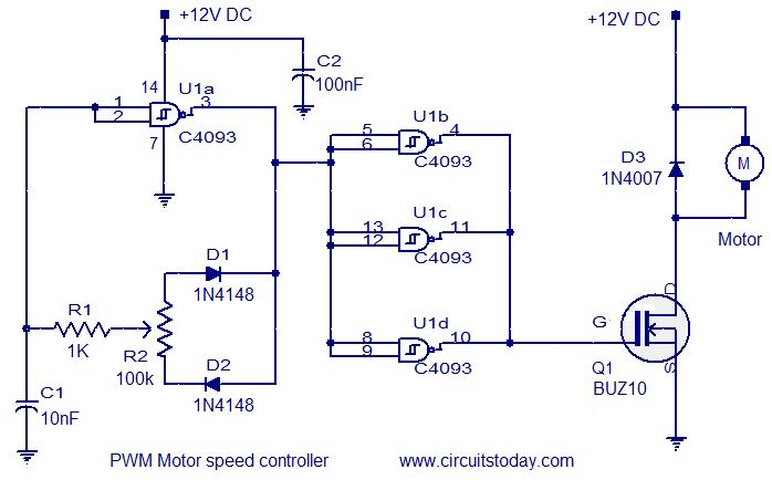
PWM motor speed controller
This circuit is designed based on a request from Mr. Vinoth in India. The requirement is for a 12V/5A DC fan motor controller. The circuit utilizes the quad 2-input Schmitt trigger IC CD4093 as its core component. Among the four...
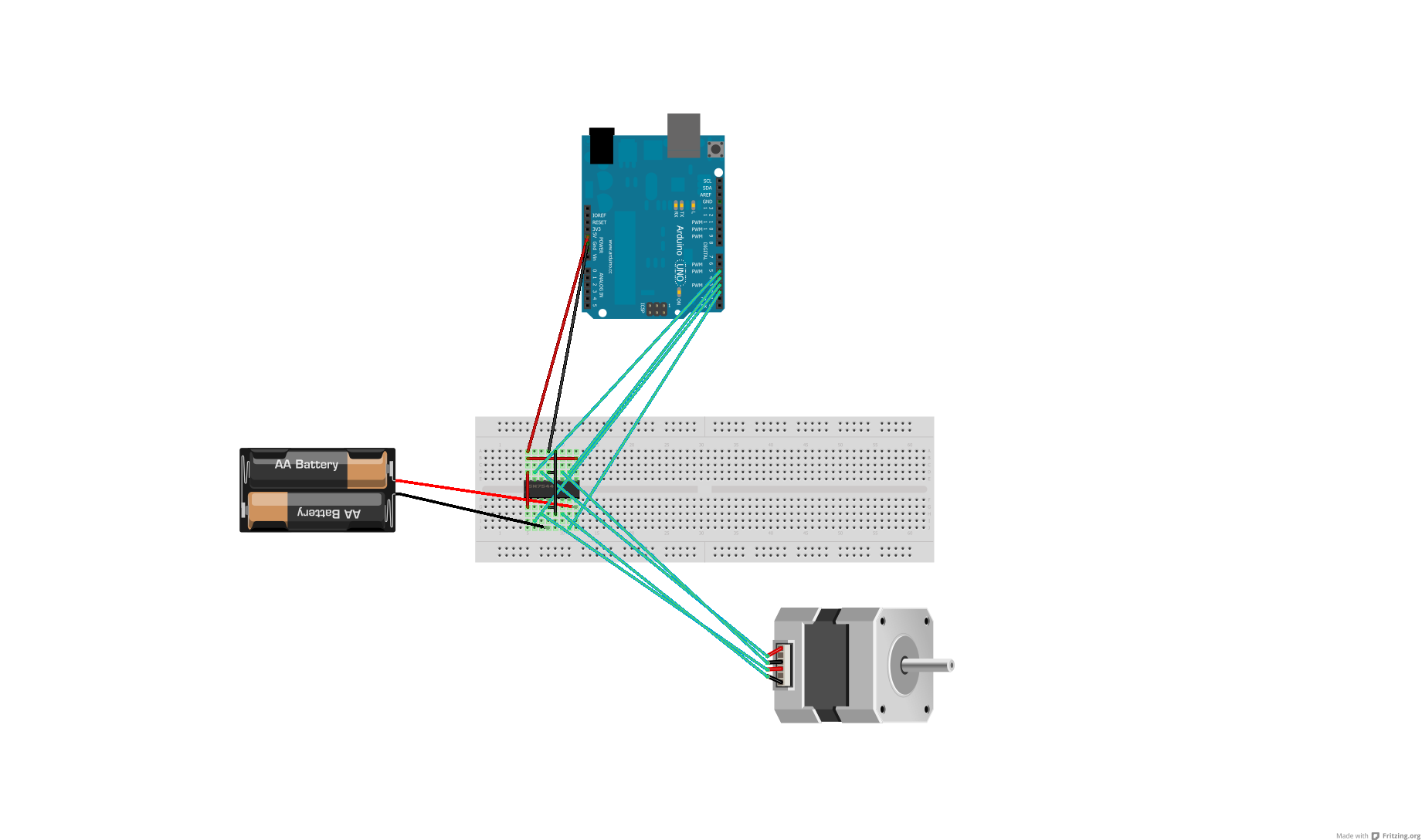
Voltage regulator or resistors to change voltages for motors
After conducting some research, it was found that voltage can be adjusted using either a voltage regulator chip or resistors. Several scenarios require reducing the voltage for motors, prompting a question about the appropriate method for each application. An H-Bridge...
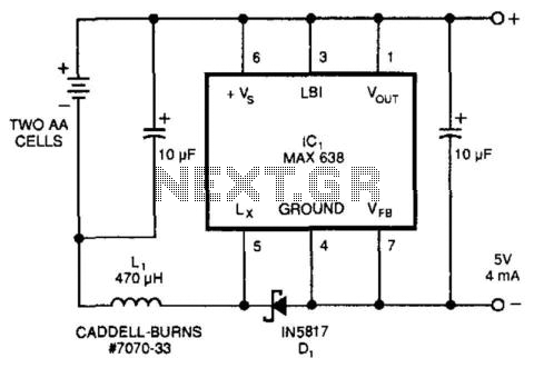
Common Hot-Lead Regulator
This circuit derives 5 V DC from 2 AA cells, even at their end-life voltages of 1.05 V, and is approximately 80% efficient, providing 5 V at 4 mA from 2.1 V at 11 mA. IC1 is manufactured by Maxim...
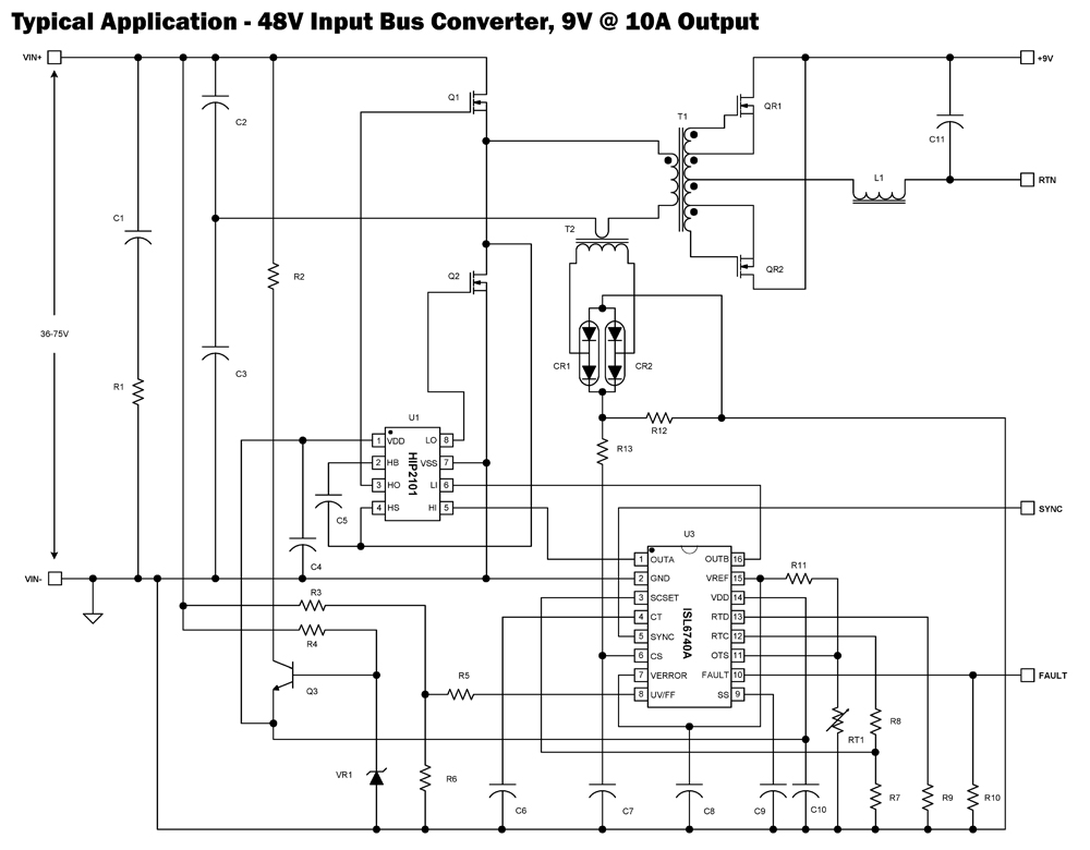
ISL6740A Flexible Double-Ended Voltage-Mode PWM Controller with Voltage Feed Forward
The ISL6740A is an enhanced PWM controller that incorporates built-in voltage feed forward functionality. It is pin and feature compatible with the ISL6740 double-ended pulse width modulation (PWM) voltage-mode controller, facilitating straightforward drop-in replacement in existing designs. Voltage feed forward...
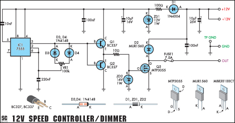
12v speed controllerdimmer
This versatile circuit functions as a speed controller for a 12V motor with a continuous rating of up to 5A or as a dimmer for a 12V halogen or standard incandescent lamp with a maximum rating of 50W. It adjusts...

12V DC Dual Power Supply Circuit with IC 7812&7912
The 78W series voltage regulators are designed to handle an input voltage of approximately 35V, while the 24V type can withstand up to 40V. It should be noted that these regulators will not operate effectively with a significant input-output voltage...