


iphone battery pack
#iphone
#battery pack
#alkaline batteries
#USB socket
#power supply
#DIY
#soldering
#portable charger
#electronics
#Apple device
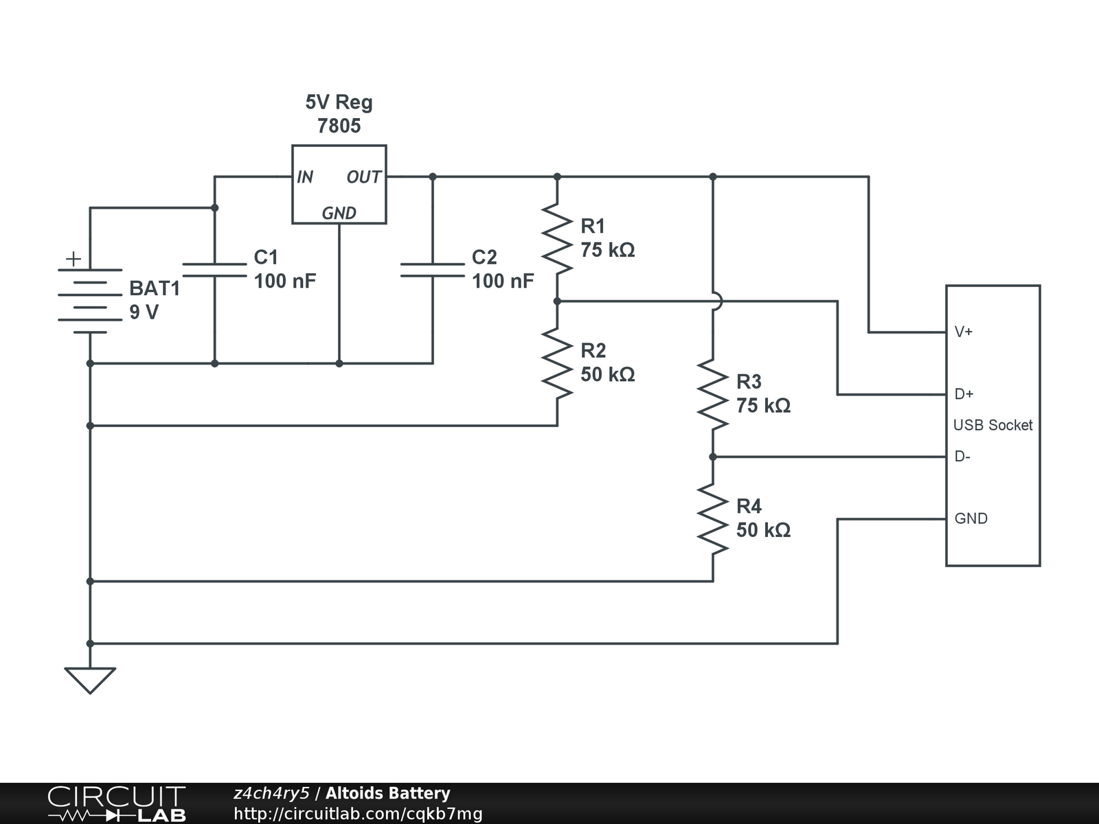
Description: Instructions for creating a battery pack for Apple devices powered by standard alkaline batteries are provided. This overview outlines the circuit design for the battery pack, with detailed casing instructions to follow in a subsequent section. Note: When soldering the USB socket, position the open part to the right and the connector pins to the left, as indicated in the schematic. Inside the socket, there are two sections: a hollow section and a section with pins. Ensure the hollow section is positioned at the bottom and the pins at the top. This circuit is essential for compatibility with Apple devices, requiring specific voltage levels: 5V on the first pin, 2V on the second and third pins, and ground on the fourth pin. Step-by-step soldering instructions for each component cannot be provided due to variations in the pre-made copper insertions on different PCB boards. Any battery with a voltage above 6 volts can be utilized for this circuit. To operate the circuit, connect a USB charger cord to the battery pack and then to the Apple device.
The design of the battery pack circuit for Apple devices involves several critical components and configurations to ensure proper functionality. The circuit primarily consists of a USB socket, resistors, capacitors, a voltage regulator, and the alkaline batteries. The USB socket is the interface for connecting the charger to the Apple device, and it must be soldered correctly to maintain the required pin configuration.
In terms of power supply, standard alkaline batteries can be used to create a battery pack that outputs a voltage suitable for charging Apple devices. The circuit requires a stable output of 5V from the first pin of the USB socket, which is necessary for the device's charging process. The second and third pins must be set to 2V, which may serve specific signaling purposes for the device. The fourth pin is designated as ground, completing the circuit.
When assembling the circuit, attention must be given to the orientation of the USB socket, ensuring that the hollow section is at the bottom and the pins are at the top. This orientation is crucial for the proper alignment of connections. The choice of PCB board can affect the soldering process, as different boards may have varying copper insertions that dictate where components can be attached.
For the power source, any battery rated above 6 volts can be utilized, providing flexibility in battery selection. However, care must be taken to ensure that the voltage does not exceed the limits that the Apple device can handle. Once the battery pack is assembled, the user can connect a USB charger cord to the battery pack and subsequently to the Apple device, enabling charging functionality.
This overview serves as a foundational guide for the construction of a battery pack circuit tailored for Apple devices, emphasizing the importance of proper soldering techniques and component configuration to achieve a reliable power supply.How to create a Battery pack for your Apple device that is powered by normal Alkaline batteries. This will be a general overview of building the circuit for the battery pack and the detailed instructions for the case will be given in part 2 of this post. NOTE: When soldering the USB socket, face the open part to the right with the connector pins facing left, as in the schematic.
Inside the socket, you will see that there are "2 halves", a hollow half and a half with pins. Make sure that the hollow half is on the bottom and the pins are on the top. This circuit is necessary for the charger to be accepted by the Apple device. Basically, the USB socket must have exactly 5V on the first pin, 2V on the second and third pins, and ground on the fourth pin. I cannot give step-by-step instructions for soldering in each and every resistor, wire, capacitor, regulator, ect.
because depending on the type of PCB board you buy, the pre-made copper insertions on the back of the board are different. Any type of battery above 6 volts will work for this circuit. To use this circuit, just plug in your USB charger cord and plug it into your Apple device.
The design of the battery pack circuit for Apple devices involves several critical components and configurations to ensure proper functionality. The circuit primarily consists of a USB socket, resistors, capacitors, a voltage regulator, and the alkaline batteries. The USB socket is the interface for connecting the charger to the Apple device, and it must be soldered correctly to maintain the required pin configuration.
In terms of power supply, standard alkaline batteries can be used to create a battery pack that outputs a voltage suitable for charging Apple devices. The circuit requires a stable output of 5V from the first pin of the USB socket, which is necessary for the device's charging process. The second and third pins must be set to 2V, which may serve specific signaling purposes for the device. The fourth pin is designated as ground, completing the circuit.
When assembling the circuit, attention must be given to the orientation of the USB socket, ensuring that the hollow section is at the bottom and the pins are at the top. This orientation is crucial for the proper alignment of connections. The choice of PCB board can affect the soldering process, as different boards may have varying copper insertions that dictate where components can be attached.
For the power source, any battery rated above 6 volts can be utilized, providing flexibility in battery selection. However, care must be taken to ensure that the voltage does not exceed the limits that the Apple device can handle. Once the battery pack is assembled, the user can connect a USB charger cord to the battery pack and subsequently to the Apple device, enabling charging functionality.
This overview serves as a foundational guide for the construction of a battery pack circuit tailored for Apple devices, emphasizing the importance of proper soldering techniques and component configuration to achieve a reliable power supply.How to create a Battery pack for your Apple device that is powered by normal Alkaline batteries. This will be a general overview of building the circuit for the battery pack and the detailed instructions for the case will be given in part 2 of this post. NOTE: When soldering the USB socket, face the open part to the right with the connector pins facing left, as in the schematic.
Inside the socket, you will see that there are "2 halves", a hollow half and a half with pins. Make sure that the hollow half is on the bottom and the pins are on the top. This circuit is necessary for the charger to be accepted by the Apple device. Basically, the USB socket must have exactly 5V on the first pin, 2V on the second and third pins, and ground on the fourth pin. I cannot give step-by-step instructions for soldering in each and every resistor, wire, capacitor, regulator, ect.
because depending on the type of PCB board you buy, the pre-made copper insertions on the back of the board are different. Any type of battery above 6 volts will work for this circuit. To use this circuit, just plug in your USB charger cord and plug it into your Apple device.
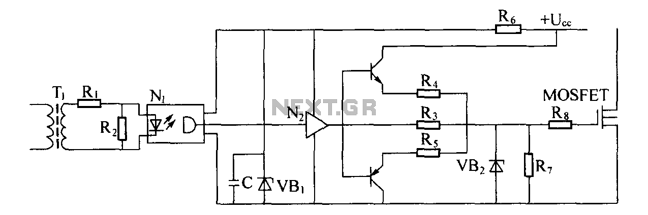
Switching power supply drive circuit
Driver circuit diagram: The primary function of the driver circuit is to serve as a variable width pulse width modulator output power amplifier, providing a drive signal to high voltage power switching devices. The driving circuit typically plays a role...
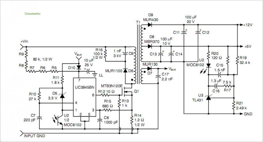
switching power supply schematic
This post summarizes the work of experts in switching power supply schematic diagrams who are thoroughly knowledgeable about all aspects of the subject.
Switching power supplies are crucial components in modern electronic devices, providing efficient voltage regulation and power conversion. The...
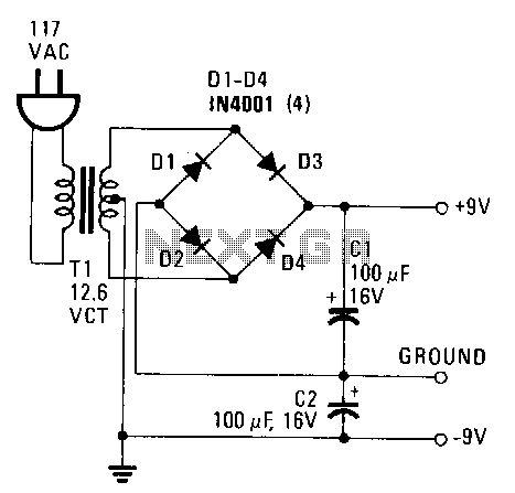
Simple-power-supply
This power supply provides both +9 V and -9 V outputs to replace two 9-V batteries. The rectifier circuit consists of two separate full-wave rectifiers, each connected to the secondary winding of the transformer. The first full-wave rectifier, made up...
Circuit diagrams and Schematic
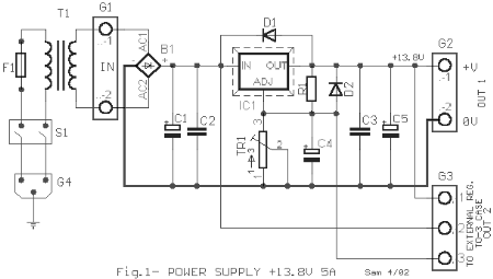
This AC to DC power supply can output 5A in continuous operation and 12A peak current. This type of DC power supply uses a PCB, allowing for two case types for IC1: TO-220 or TO-3. The regulation of this 12-volt...
Sanyo 83P switching power supply circuit diagram
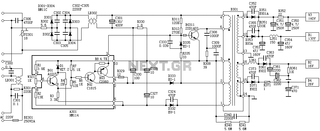
Oscillation: The positive terminal voltage of C310 is approximately 300V. The resistors R311 and R312 are connected to the switch BG311 at the B pole, while the B301 winding via the switching transformer (4) and (6) is connected to the...
35W switching power supply circuit having a set-top box output of 5
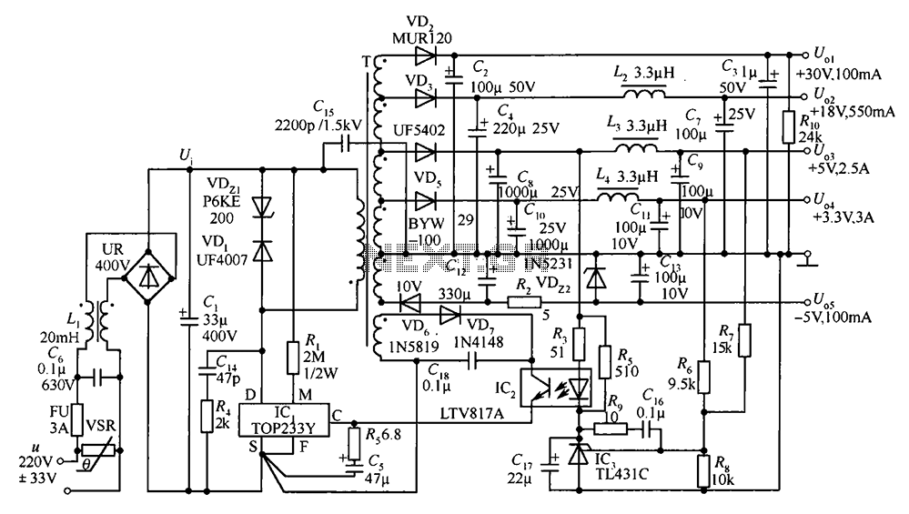
A 35W switching power supply circuit designed for a set-top box output is depicted in Figure 5. It features five distinct voltage outputs: Uo1 (+30V, 100mA), Uo2 (+18V, 550mA), Uo3 (+5V, 2.5A), Uo4 (+3.3V, 3A), and Uo5 (-5V, 100mA). The...
Power Supply for P.A. Class40
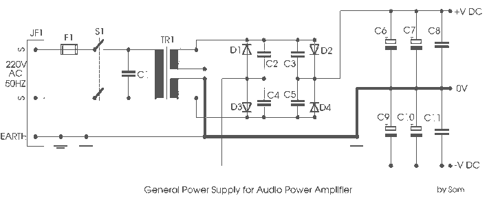
For its maximum result, the final stage of the amplifier should have the proper power supply, as the flowing currents are very high. A Class A amplifier requires attention. These are the rules for the power supply for the Class...
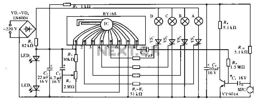
Lighting controller circuit
The circuit operates with a controller that includes a power supply circuit, a control circuit, and an audio amplifier, which are three distinct components. The power circuit comprises diodes VD1 to VD4, resistor R1, capacitor C1, LED1, LED2, and additional...
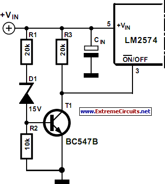
Soft Start For Switching Power Supply
A switching power supply that has an output voltage significantly lower than its input voltage exhibits a unique characteristic: the current drawn from the supply is less than the output current. However, the input power (UI) is, naturally, greater than...