


Lead Acid Battery Charger with voltmeter
#lead acid battery
#voltmeter
#LM3914
#charging process
#digital voltmeter
#trimmer potentiometer
#voltage adjustment
#LED indicator
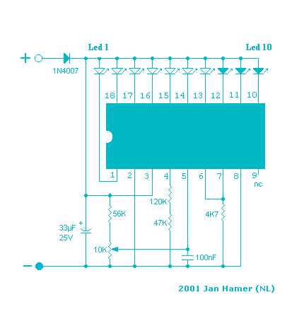
Description: This simple circuit makes it possible to monitor the charging process to a higher level. If you need more information then check out the LM3914 Datasheet. Final adjustments are simple and the only thing needed is a digital voltmeter for the necessary accuracy. Connect an input voltage of 12.65 volt between the positive and negative poles and adjust the 10K trimmer potentiometer until Led 10 lights up. Lower the voltage and in sequence all other Led's will light up. Check that Led 1 lights up at approximately 11.89 volts. At 12.65 volt and higher the battery is fully charged, and at 11.89 is considered 'empty'. The green Led's indicate that the battery capacity is more than 50%, the yellow Led's indicate a capacity of 30% - 50% and the red Led's less that 30%. This circuit, with the components shown, uses less than 10mA. Of course you can adapt this circuit to your own needs by making small modifications. The circuits above is set for 'DOT' mode, meaning only one Led at a time will be lit. If you wish to use the 'BAR' mode, then connect pin 9 to the positive supply rail, but obviously with increased current consumption. The LED brightness can be adjusted up- or down by choosing a different value for the 4K7 resistor connected at pin 6/7. You can also change the monitoring voltage level. For example, let's say you wanted to change to 10 - 13 volt, you connect 13volt to the input (+ and -) and adjust the 10K potentiometer until Led 10 lights up. Change temporarily the resistors at pin 4 with a 200 Kilo-ohm potentiometer and reconnect a voltage from 10 Volt to the input. Now, re-adjust the 200K potentiometer until Led 1 lights up. When you are satisfied with the adjustment, feel free to exchange the 200K potentiometer with resistors again (after measuring the resistance from the pot, obviously). The diode 1N4007 was included to protect the circuit from a wrong polarity connection. It is however strongly recommended to connect the monitor directly to the battery, in principle a connection to the cigarette lighter would suffice but for reasons unknown at this time the voltage at that point is 0.2 volt lower than the voltage measured directly on the battery. Could be some residual resistance caused by ignition switch and path through the fuse?
The described circuit utilizes the LM3914 LED bar graph/LED dot display driver IC to visually indicate the state of charge of a battery, typically within the range of 10 to 13 volts. The circuit is designed to operate with minimal power consumption, drawing less than 10mA, making it suitable for battery-operated applications.
The primary components include the LM3914, a 10K trimmer potentiometer for calibration, and a series of LEDs to represent different voltage levels. The circuit is configured to operate in 'DOT' mode by default, where only one LED is illuminated at a time corresponding to the battery voltage. For applications requiring a more continuous display, the circuit can be switched to 'BAR' mode by connecting pin 9 to the positive supply rail, which will increase the current consumption.
To calibrate the circuit, an input voltage of 12.65 volts is applied across the designated input terminals. The 10K trimmer potentiometer is adjusted until the 10th LED lights up, indicating a fully charged battery. Lowering the input voltage sequentially illuminates the other LEDs, with the first LED lighting up at approximately 11.89 volts, indicating a low battery state.
The circuit includes color-coded LEDs to provide a clear visual representation of battery capacity: green LEDs indicate more than 50% charge, yellow LEDs represent 30% to 50% charge, and red LEDs indicate less than 30% charge.
For users requiring different voltage monitoring levels, adjustments can be made by connecting a higher voltage (e.g., 13 volts) to the input and recalibrating the potentiometer. Additionally, the resistors connected to pin 4 can be temporarily replaced with a 200K potentiometer for further adjustments, allowing for fine-tuning of the voltage thresholds.
A diode (1N4007) is included in the circuit to protect against reverse polarity connections, ensuring the longevity and reliability of the device. It is advisable to connect the circuit directly to the battery terminals for accurate voltage readings, as connections through other points, such as a cigarette lighter, may introduce voltage drops due to resistance in the wiring.
Overall, this circuit provides a straightforward and effective solution for monitoring battery voltage, with the flexibility for customization to meet specific user requirements.This simple circuit makes it posible to monitor the charging process to a higher level. If you need more information then check out the LM3914 Datasheet. Final adjustsments are simple and the only thing needed is a digital voltmeter for the necessary accuracy. Connect an input voltage of 12.65 volt between the positive and negative poles and adjust the 10K trimmer potentiometer until Led 10 lights up.
Lower the voltage and in sequence all other Led's will light up. Check that Led 1 lights up at approximately 11.89 volts. At 12.65 volt and higher the battery is fully charged, and at 11.89 is considered 'empty'. The green Led's indicate that the battery capacity is more than 50%, the yellow Led's indicate a capacity of 30% - 50% and the red Led's less that 30%. This circuit, with the components shown, uses less than 10mA. Ofcourse you can adapt this circuit to your own needs by making small modifications. The circuits above is set for 'DOT' mode, meaning only one Led at a time will be lit. If you wish to use the 'BAR' mode, then connect pin 9 to the positive supply rail, but obviously with increased current consumption.
The LED brightness can be adjusted up- or down by choosing a different value for the 4K7 resistor connected at pin 6/7. You can also change the to monitoring voltage level. For example, let's say you wanted to change to 10 - 13 volt, you connect 13volt to the input (+ and -) and adjust the 10K potentiometer until Led 10 lights up.
Change temporarily the resistors at pin 4 with a 200 Kilo-ohm potentiometer and reconnect a voltage from 10 Volt to the input. Now, re-adjust the 200K potentiometer until Led 1 lights up. When you are satisfied with the adjustment, feel free to exchange the 200K potentiometer with resistors again.(after measuring the resistance from the pot, obviously).
The diode 1N4007 was included to protect the circuit from a wrong polarity connection. It is however strongly recommended to connect the monitor directly to the battery, in principle a connection to the cigarrette lighter would suffice but for reasons unknown at this time the voltage at that point is 0.2 volt lower than the voltage measured directly on the battery. Could be some residual resistance caused by ignition switch and path through the fuse?
The described circuit utilizes the LM3914 LED bar graph/LED dot display driver IC to visually indicate the state of charge of a battery, typically within the range of 10 to 13 volts. The circuit is designed to operate with minimal power consumption, drawing less than 10mA, making it suitable for battery-operated applications.
The primary components include the LM3914, a 10K trimmer potentiometer for calibration, and a series of LEDs to represent different voltage levels. The circuit is configured to operate in 'DOT' mode by default, where only one LED is illuminated at a time corresponding to the battery voltage. For applications requiring a more continuous display, the circuit can be switched to 'BAR' mode by connecting pin 9 to the positive supply rail, which will increase the current consumption.
To calibrate the circuit, an input voltage of 12.65 volts is applied across the designated input terminals. The 10K trimmer potentiometer is adjusted until the 10th LED lights up, indicating a fully charged battery. Lowering the input voltage sequentially illuminates the other LEDs, with the first LED lighting up at approximately 11.89 volts, indicating a low battery state.
The circuit includes color-coded LEDs to provide a clear visual representation of battery capacity: green LEDs indicate more than 50% charge, yellow LEDs represent 30% to 50% charge, and red LEDs indicate less than 30% charge.
For users requiring different voltage monitoring levels, adjustments can be made by connecting a higher voltage (e.g., 13 volts) to the input and recalibrating the potentiometer. Additionally, the resistors connected to pin 4 can be temporarily replaced with a 200K potentiometer for further adjustments, allowing for fine-tuning of the voltage thresholds.
A diode (1N4007) is included in the circuit to protect against reverse polarity connections, ensuring the longevity and reliability of the device. It is advisable to connect the circuit directly to the battery terminals for accurate voltage readings, as connections through other points, such as a cigarette lighter, may introduce voltage drops due to resistance in the wiring.
Overall, this circuit provides a straightforward and effective solution for monitoring battery voltage, with the flexibility for customization to meet specific user requirements.This simple circuit makes it posible to monitor the charging process to a higher level. If you need more information then check out the LM3914 Datasheet. Final adjustsments are simple and the only thing needed is a digital voltmeter for the necessary accuracy. Connect an input voltage of 12.65 volt between the positive and negative poles and adjust the 10K trimmer potentiometer until Led 10 lights up.
Lower the voltage and in sequence all other Led's will light up. Check that Led 1 lights up at approximately 11.89 volts. At 12.65 volt and higher the battery is fully charged, and at 11.89 is considered 'empty'. The green Led's indicate that the battery capacity is more than 50%, the yellow Led's indicate a capacity of 30% - 50% and the red Led's less that 30%. This circuit, with the components shown, uses less than 10mA. Ofcourse you can adapt this circuit to your own needs by making small modifications. The circuits above is set for 'DOT' mode, meaning only one Led at a time will be lit. If you wish to use the 'BAR' mode, then connect pin 9 to the positive supply rail, but obviously with increased current consumption.
The LED brightness can be adjusted up- or down by choosing a different value for the 4K7 resistor connected at pin 6/7. You can also change the to monitoring voltage level. For example, let's say you wanted to change to 10 - 13 volt, you connect 13volt to the input (+ and -) and adjust the 10K potentiometer until Led 10 lights up.
Change temporarily the resistors at pin 4 with a 200 Kilo-ohm potentiometer and reconnect a voltage from 10 Volt to the input. Now, re-adjust the 200K potentiometer until Led 1 lights up. When you are satisfied with the adjustment, feel free to exchange the 200K potentiometer with resistors again.(after measuring the resistance from the pot, obviously).
The diode 1N4007 was included to protect the circuit from a wrong polarity connection. It is however strongly recommended to connect the monitor directly to the battery, in principle a connection to the cigarrette lighter would suffice but for reasons unknown at this time the voltage at that point is 0.2 volt lower than the voltage measured directly on the battery. Could be some residual resistance caused by ignition switch and path through the fuse?
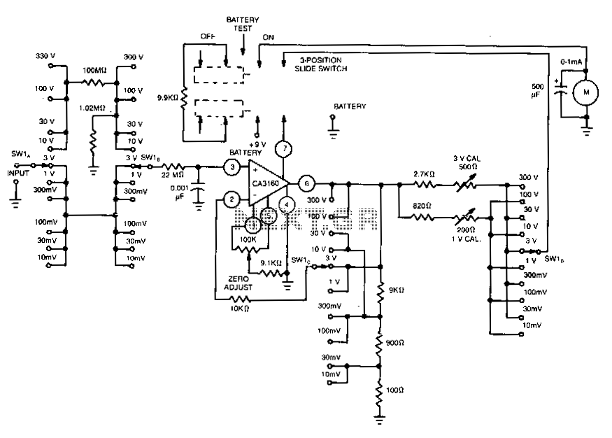
High-input-resistance-dc-voltmeter
This voltmeter utilizes several beneficial characteristics of the CA3160 BiMOS operational amplifier. It offers voltage measurement capabilities ranging from 10 mV to 300 V. The circuit is powered by a single 8.4-V mercury battery and, at zero input, consumes approximately...
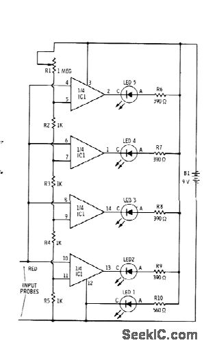
BAR GRAPH READOUT VOLTMETER
Sections of the RS339 quad comparator each drive an LED to indicate four different input voltage levels. LED 1 is connected to ground to serve as a zero indicator. The resistors depicted are intended for Radio Shack 276-041 red LEDs;...
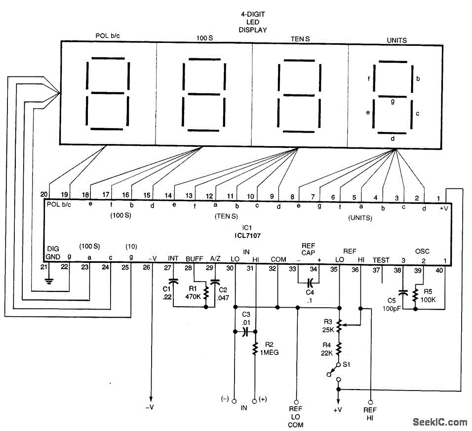
DIGITAL VOLTMETER CIRCUIT
A basic digital voltmeter circuit utilizing the Harris Semiconductor ICL7107 is presented. It operates within a 2-V range. Calibration involves applying a known voltage of 1.2 V to the input and adjusting resistor R3 to achieve an accurate reading on...
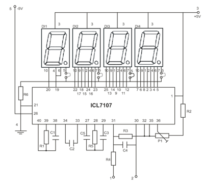
Led display digital Voltmeter
The device is designed as a panel meter suitable for use in DC power supplies or any application that requires accurate voltage indication. It utilizes the CL7107 integrated circuit (IC) from INTERSIL, which is housed in a 40-pin package and...
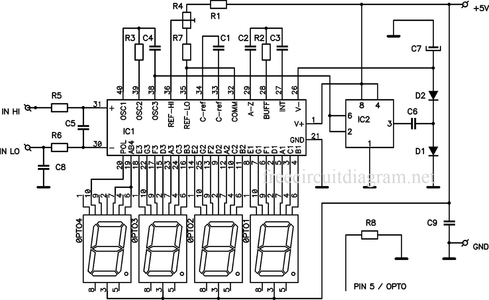
Digital LED Voltmeter Using ICL7107
This circuit is a digital voltmeter diagram featuring an LED display. It is designed for measuring the output voltage of a DC power supply. The voltmeter incorporates a 3.5-digit LED display along with a negative voltage indicator. It is capable...
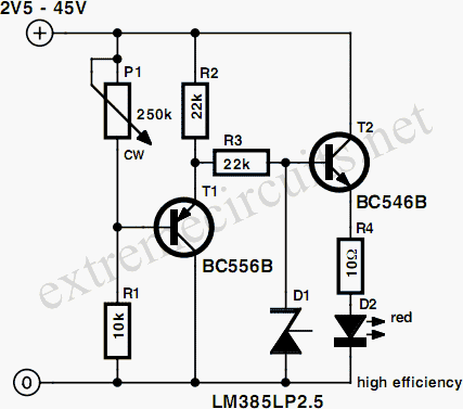
Simple Voltmeter
This circuit provides a straightforward method for measuring the voltage of a low-impedance voltage source. It operates as follows: P1, a 1-W potentiometer, acts as a voltage divider in conjunction with resistor R1. The voltage at their junction is buffered...
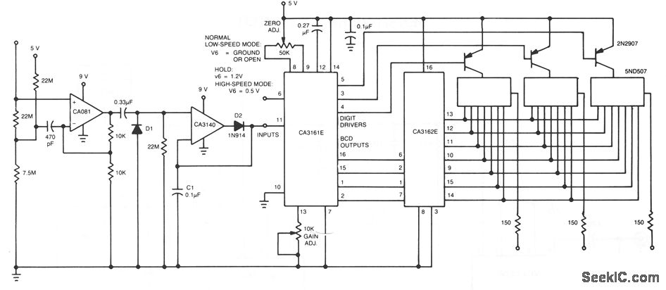
AC VOLTMETER
The CA081 and CA3140 BiMOS operational amplifiers provide minimal loading on the circuits being measured. The wide bandwidth and high slew rate of the CA081 enable the meter to operate at frequencies up to 0.5 MHz.
The CA081 and CA3140 are...
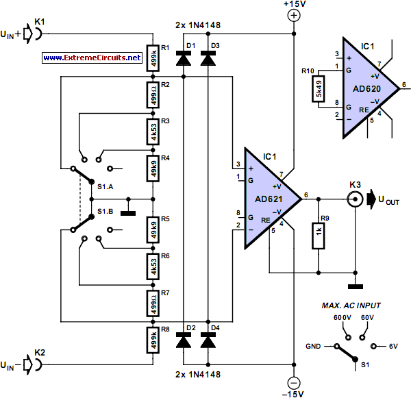
meter adaptor with symmetrical
Unlike a standard voltmeter, the input of an oscilloscope typically has one side (GND) connected to ground through the mains lead. This connection can lead to significant issues when the measuring probe is attached to a circuit that is also...
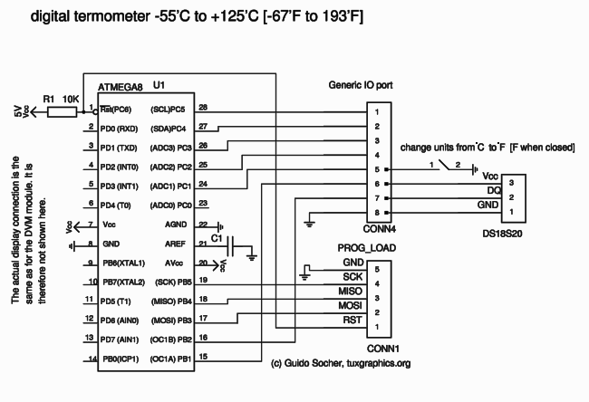
three digit display.
The Mini 3-digit display, also known as the "DVM-module" (digital voltmeter module), can be easily tuned and modified due to firmware control. Key advantages of this module include an internal reference voltage of 2.56V in the ATmega8 microcontroller. By adding...