


lithium battery charger
#lithium battery
#multi-cell
#charging system
#power supply
#series-connected
#battery pack
#charger circuit
#lithium-ion
#battery management
#energy storage
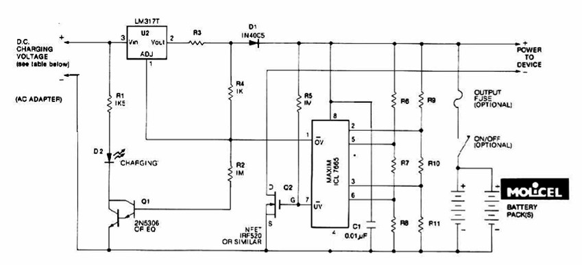
Description: The charging system described is designed for multi-cell lithium battery packs comprising two to six series-connected cells or series/parallel configurations. The schematic diagram originates from the lithium battery charger power supply circuit. This circuit is specifically intended for charging lithium batteries. It utilizes two integrated circuits: the voltage regulator LM317T and the IC L7665, which alerts microprocessors to overvoltage and undervoltage conditions. The charging process is conducted at a constant current of 60 mA for AA cells, reaching a cutoff voltage of 2.4 V per cell, at which point the charge should be terminated.
The lithium battery charger circuit is engineered to accommodate various configurations of lithium battery packs, allowing for flexibility in applications ranging from consumer electronics to larger battery systems. The LM317T voltage regulator is a linear regulator that provides a stable output voltage, adjustable via external resistors, which can be tailored to meet the specific voltage requirements of the battery pack being charged.
The IC L7665 serves a critical role in monitoring the battery voltage, ensuring that the charging process remains within safe limits. It provides overvoltage and undervoltage protection, which is essential for the longevity and safety of lithium batteries. By signaling the microprocessor when the voltage exceeds or drops below predetermined thresholds, it helps prevent potential damage to the cells.
During the charging phase, the circuit maintains a constant current of 60 mA, which is optimal for AA lithium cells. This controlled charging rate is crucial for preventing overheating and extending battery life. The cutoff voltage of 2.4 V per cell is a standard threshold for lithium batteries, marking the point at which charging should cease to avoid overcharging, which can lead to thermal runaway and other safety hazards.
Overall, this charging system is a reliable solution for managing the charging of multi-cell lithium battery packs, ensuring both performance and safety through careful voltage regulation and monitoring. The design is suitable for integration into various electronic devices requiring efficient and safe battery charging solutions.The charging system shown is made for multi-cell lithium battery packs of two to six series-connected cells or series/parallel arrangements. The schematic diagram come from circuit: Lithium Battery Charger power supply. Go to that page to read the explanation about above power supply related circuit diagram. This Lithium battery charger circuit is dedicated to charge lithium batteries. Ituses 2chips, voltage regulator LM317T and IC L7665 warns microprocessors ( Ps) of over voltage and unde rvoltage conditions. Charging is completed with a constant current of 60 ma for Aa cells to a cutoff voltage of 2. 4 V per cell, at which point the charge should be terminated. The.
The lithium battery charger circuit is engineered to accommodate various configurations of lithium battery packs, allowing for flexibility in applications ranging from consumer electronics to larger battery systems. The LM317T voltage regulator is a linear regulator that provides a stable output voltage, adjustable via external resistors, which can be tailored to meet the specific voltage requirements of the battery pack being charged.
The IC L7665 serves a critical role in monitoring the battery voltage, ensuring that the charging process remains within safe limits. It provides overvoltage and undervoltage protection, which is essential for the longevity and safety of lithium batteries. By signaling the microprocessor when the voltage exceeds or drops below predetermined thresholds, it helps prevent potential damage to the cells.
During the charging phase, the circuit maintains a constant current of 60 mA, which is optimal for AA lithium cells. This controlled charging rate is crucial for preventing overheating and extending battery life. The cutoff voltage of 2.4 V per cell is a standard threshold for lithium batteries, marking the point at which charging should cease to avoid overcharging, which can lead to thermal runaway and other safety hazards.
Overall, this charging system is a reliable solution for managing the charging of multi-cell lithium battery packs, ensuring both performance and safety through careful voltage regulation and monitoring. The design is suitable for integration into various electronic devices requiring efficient and safe battery charging solutions.The charging system shown is made for multi-cell lithium battery packs of two to six series-connected cells or series/parallel arrangements. The schematic diagram come from circuit: Lithium Battery Charger power supply. Go to that page to read the explanation about above power supply related circuit diagram. This Lithium battery charger circuit is dedicated to charge lithium batteries. Ituses 2chips, voltage regulator LM317T and IC L7665 warns microprocessors ( Ps) of over voltage and unde rvoltage conditions. Charging is completed with a constant current of 60 ma for Aa cells to a cutoff voltage of 2. 4 V per cell, at which point the charge should be terminated. The.
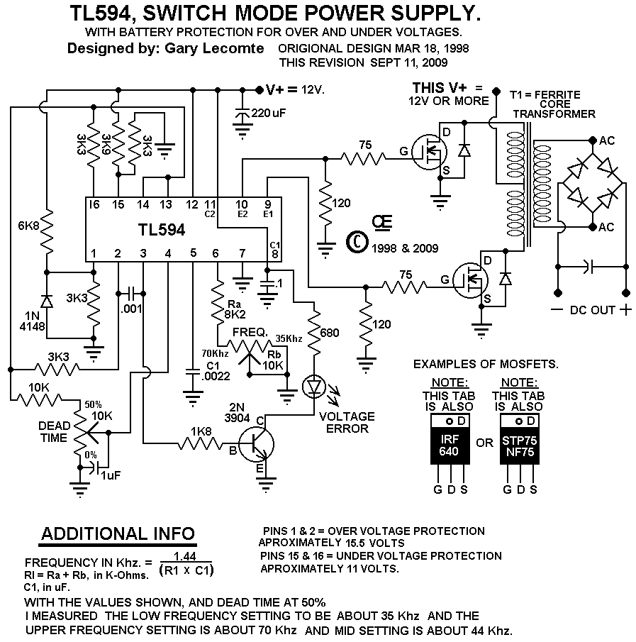
A 12 Volt Switching Power Supply
This circuit is designed for individuals needing to boost or drop a voltage. The output operates at high frequency but can be rectified and filtered to provide a DC output. When rectifying high frequencies, it is essential to utilize high-speed...
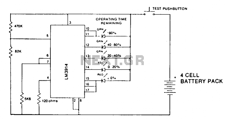
Lithium battery indicator
A state-of-charge indication of a sloping-voltage discharge can be utilized as a state-of-charge indicator. A typical voltage comparator circuit that provides a visual indication of the state of charge is presented. Components identified are for a 4-cell input voltage ranging...
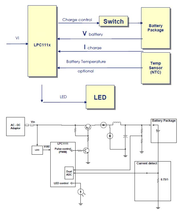
LPCzone
Rechargeable lithium-ion (Li-ion) batteries are widely used today, powering devices such as laptops, tablets, cell phones, MP3 players, digital cameras, and various portable electronics. This application note examines the use of an LPC111x microcontroller (MCU) for charging these batteries, highlighting...
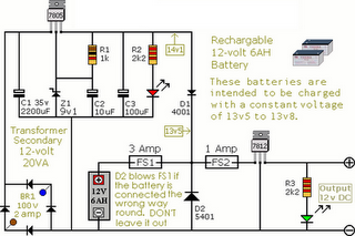
Circuit Diagram Of Alarm Power Supply
The following circuit illustrates an Alarm Power Supply Circuit Diagram. Features include a 1-amp current output, suitable for a Modular Burglar Alarm operating at 12 volts.
The Alarm Power Supply Circuit is designed to provide a stable and reliable power source...
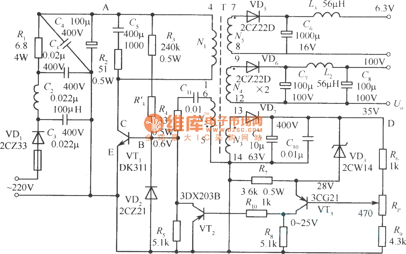
Output sampling winding isolated switching power supply
The diagram illustrates the output sampling winding of an isolated switching power supply. In the diagram, T represents a high-frequency transformer; N2 denotes the self-oscillation positive feedback winding; N3 is the error amplifier; VTS is the winding that provides the...
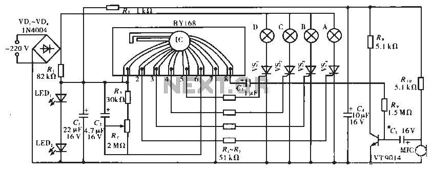
Lighting controller circuit
The circuit operates with a controller that includes a power supply circuit, a control circuit, and an audio amplifier, which are three distinct components. The power circuit comprises diodes VD1 to VD4, resistor R1, capacitor C1, LED1, LED2, and additional...
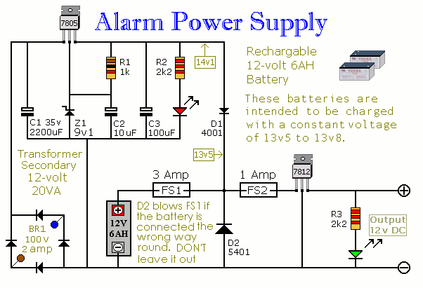
Alarm Power Supply
This Power Supply is suitable for the Modular Burglar Alarm. However, it has other applications. It is designed to provide an output of 12-volts, with a current of up to 1-amp. In the event of mains failure, the back-up battery...
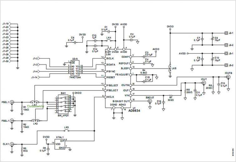
Evaluation Board For The Ad9834 Direct Digital Synthesizer
This document outlines the design of a low-cost 90 W flyback switching power supply intended for use in a multi-sync color monitor. To reduce screen interference caused by switching noise, the power supply can be automatically synchronized to the fixed...
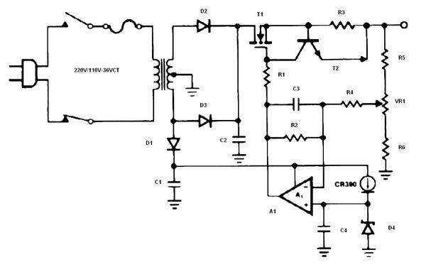
Battery charger or Power Supply 14 volt 4 ampere
The schematic diagram originates from a circuit designed as a battery charger/power supply with an output of 14V and a maximum current of 4A, utilizing the VN64GA MOSFET. This high-performance battery charger is specifically engineered for gelled electrolyte lead-acid batteries,...