


Ni-Cd Baterry Charger 12-18V
#Ni-Cd
#charger
#12-18V
#charge current selection
#polarization detection
#battery protection
#series connection
#14-hour charge
#1/10 Ah
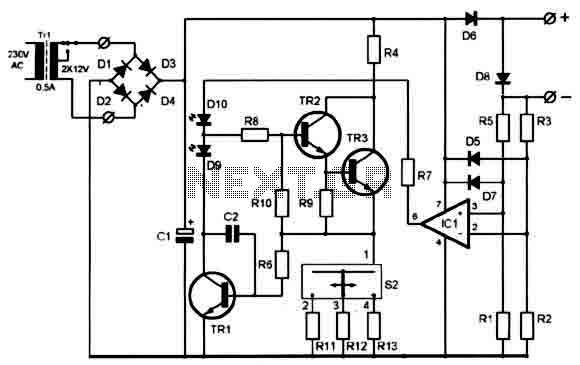
Description: A clever charger circuit that safely charges any Ni-Cd battery. It offers charge current selection, polarization detection, protection, and the ability to connect multiple batteries in series. Ni-Cd batteries can be recharged more than 1000 times before becoming unusable. The charging current should be 1/10 of the battery's capacity in ampere-hours (Ah). The batteries require 14 hours to be fully charged. The switch S2 allows for current selection at 50mA, 200mA, and 400mA. LED D10 indicates proper battery connection and checks for incorrect polarity. LED D9 serves as the charging indicator. The transformer used is a 220V/2x12V 0.5A.
This charger circuit is designed for the efficient and safe charging of Nickel-Cadmium (Ni-Cd) batteries, which are known for their longevity and ability to undergo numerous charge cycles. The circuit includes a current selection switch (S2) that allows the user to choose between three charging currents: 50mA, 200mA, and 400mA. This flexibility is particularly useful for charging batteries of varying capacities and conditions.
The circuit employs LED indicators to provide visual feedback. LED D9 serves as a charging indicator, illuminating when the circuit is actively charging a battery. LED D10 is crucial for safety; it indicates whether the battery is correctly connected and checks for any incorrect polarity, thereby preventing potential damage to the battery or the charger itself.
The transformer in this circuit is rated at 220V with dual 12V outputs, providing a maximum current of 0.5A, which is suitable for the charging requirements of Ni-Cd batteries. The design incorporates a variety of resistors and capacitors to manage current flow and stabilize voltage levels during operation.
The components list includes:
- Resistors: R1, R4, R5 are 10K ohms; R2, R3 are 100K ohms; R6, R8, R10 are 1K ohms; R7 is 820 ohms; R9 is 100 ohms; R11 is 15 ohms; R12 is 3.9 ohms; R13 is 1.8 ohms.
- Capacitors: C1 is a 1000µF/40V capacitor, providing necessary smoothing for the power supply; C2 is a 470pF capacitor, likely used for high-frequency noise filtering.
- Diodes: D1-D4 and D6 are 1N4001 to 1N4007 diodes, which are used for rectification; D7 and D8 are 1N4148 diodes, typically used for signal routing or protection.
- LEDs: D9 and D10 are standard LEDs for visual indicators.
- Integrated Circuit: IC is a 741 operational amplifier, which may be used for voltage regulation or current sensing.
- Transistors: TR1 is a BC548, TR2 is a BD137, and TR3 is a 2N3055, which are used for switching and amplification within the circuit.
This detailed configuration ensures that the charger operates efficiently, providing a safe and reliable means to recharge Ni-Cd batteries while maximizing their lifespan.A clever charger circuit that safely can charge any Ni-Cd battery. Offers charge current sellection, polarization detection and protection and the ability to connect many batterys in siries. Ni-Cd bateries can be recharged more than 1000 times before become useless. the charging current shoud be the 1/10 of the (Ah) of the battery. The bateries need 14 hours to be fully charged.. Swhitch S2 is the current selection as folows: 50mA, 200mA and 400mA. LED D10 is the indicator for proper batery connection and/or wrong polarity checking. LED D9 is the charging indicator. The transformer is a 220V/2x12V 0.5A. PARTS: R1,R4,R5=10K R2,R3=100K R6,R8,R10=1K R7=820 R9=100 R11=15 R12=3,9 R13=1,8 C1=1000uF/40v C2=470pf D1-D4,D6=1n4001-7 D7,D8=1n4148 D9,D10=LED IC=741 TR1=BC548 TR2=BD137 TR3=2N3055
This charger circuit is designed for the efficient and safe charging of Nickel-Cadmium (Ni-Cd) batteries, which are known for their longevity and ability to undergo numerous charge cycles. The circuit includes a current selection switch (S2) that allows the user to choose between three charging currents: 50mA, 200mA, and 400mA. This flexibility is particularly useful for charging batteries of varying capacities and conditions.
The circuit employs LED indicators to provide visual feedback. LED D9 serves as a charging indicator, illuminating when the circuit is actively charging a battery. LED D10 is crucial for safety; it indicates whether the battery is correctly connected and checks for any incorrect polarity, thereby preventing potential damage to the battery or the charger itself.
The transformer in this circuit is rated at 220V with dual 12V outputs, providing a maximum current of 0.5A, which is suitable for the charging requirements of Ni-Cd batteries. The design incorporates a variety of resistors and capacitors to manage current flow and stabilize voltage levels during operation.
The components list includes:
- Resistors: R1, R4, R5 are 10K ohms; R2, R3 are 100K ohms; R6, R8, R10 are 1K ohms; R7 is 820 ohms; R9 is 100 ohms; R11 is 15 ohms; R12 is 3.9 ohms; R13 is 1.8 ohms.
- Capacitors: C1 is a 1000µF/40V capacitor, providing necessary smoothing for the power supply; C2 is a 470pF capacitor, likely used for high-frequency noise filtering.
- Diodes: D1-D4 and D6 are 1N4001 to 1N4007 diodes, which are used for rectification; D7 and D8 are 1N4148 diodes, typically used for signal routing or protection.
- LEDs: D9 and D10 are standard LEDs for visual indicators.
- Integrated Circuit: IC is a 741 operational amplifier, which may be used for voltage regulation or current sensing.
- Transistors: TR1 is a BC548, TR2 is a BD137, and TR3 is a 2N3055, which are used for switching and amplification within the circuit.
This detailed configuration ensures that the charger operates efficiently, providing a safe and reliable means to recharge Ni-Cd batteries while maximizing their lifespan.A clever charger circuit that safely can charge any Ni-Cd battery. Offers charge current sellection, polarization detection and protection and the ability to connect many batterys in siries. Ni-Cd bateries can be recharged more than 1000 times before become useless. the charging current shoud be the 1/10 of the (Ah) of the battery. The bateries need 14 hours to be fully charged.. Swhitch S2 is the current selection as folows: 50mA, 200mA and 400mA. LED D10 is the indicator for proper batery connection and/or wrong polarity checking. LED D9 is the charging indicator. The transformer is a 220V/2x12V 0.5A. PARTS: R1,R4,R5=10K R2,R3=100K R6,R8,R10=1K R7=820 R9=100 R11=15 R12=3,9 R13=1,8 C1=1000uF/40v C2=470pf D1-D4,D6=1n4001-7 D7,D8=1n4148 D9,D10=LED IC=741 TR1=BC548 TR2=BD137 TR3=2N3055
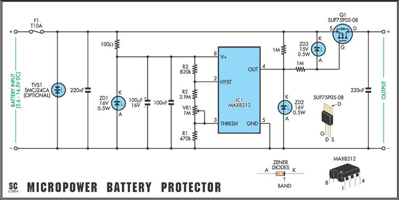
Versatile Micropower Battery Protector circuit
Protect expensive batteries from discharge damage with this mini-sized electronic cutout switch. It uses virtually no power and can be built to suit a wide range of battery voltages.
The mini-sized electronic cutout switch serves as a crucial component in battery...
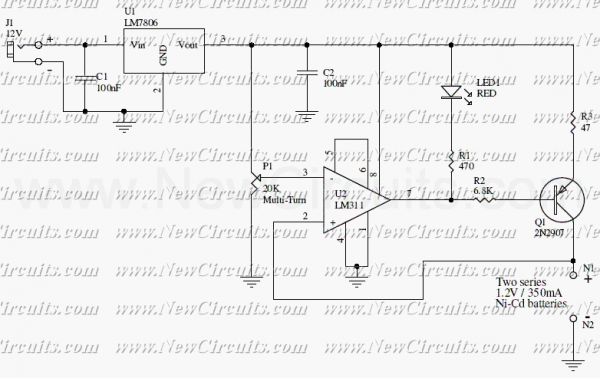
Ni-Cd Battery Automatic Charger
The circuit presented in the above schematic has been designed to charge automatically two series 350mAh "AAA" size batteries. Set the 20KOhms multiturn potentiometer to get a 2.78V on the 3rd pin of the LM311 which is a comparator. So...
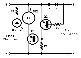
Broken Charger-connection Alert
The above circuit can be useful to detect if the load of any battery charger or plug-in adaptor supply is not properly connected. The load can be a set of batteries to be charged or any other type of battery...
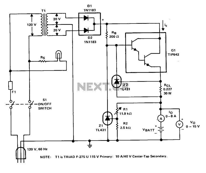
Charger circuit V
The charger operates with a charging voltage of 2.4 V per cell, aligning with the recommendations of most manufacturers. The circuit delivers a charging voltage of 14.4 V (6 cells at 2.4 V per cell) in a pulsed manner at...
Broken Charger-connection Alert
The above circuit can be useful to detect if the load of any battery charger or plug-in adaptor supply is not properly connected. The load can be a set of batteries to be charged or any other type of battery...
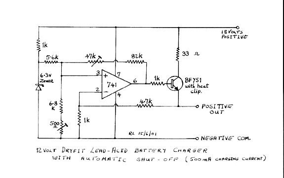
charger
The circuit was constructed on a Vero board and tested with a large electrolytic capacitor in place of a battery. A 500-ohm preset resistor determines the output voltage, while a 47k preset resistor regulates the hysteresis and establishes the voltage...
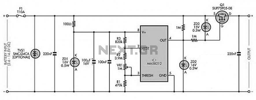
Multifunctional Battery Protector
The circuit is designed to prevent over-voltage conditions in a battery during charging. It operates automatically to charge and recharge with a very low power consumption of less than 20mA, making it suitable for use with batteries rated between 4.8V...
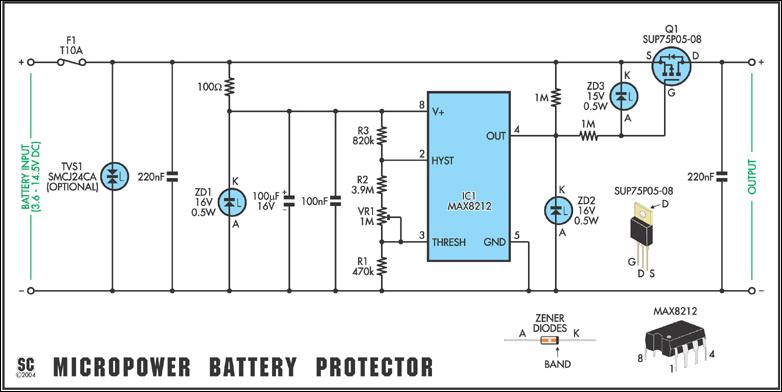
Versatile Micropower Battery Protector
In May 2002, Silicon Chip introduced the "Battery Guardian," a project aimed at safeguarding 12V car batteries from over-discharge. This unit has gained significant popularity and remains available from kit suppliers. The new design does not replace the Battery Guardian...
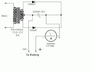
simple accu charger circuit
The Accu charger circuit is straightforward and simple to construct, requiring no more than ten components. In addition to its ease of assembly, this charger circuit is also cost-effective and highly efficient. The circuit requires a power supply from a...