


Nicad-batterv-protection-circuit
#NiCad
#battery protection
#voltage sensor
#transistor
#voltage reference
#cell reversal
#low-current
#zener diode
#load control
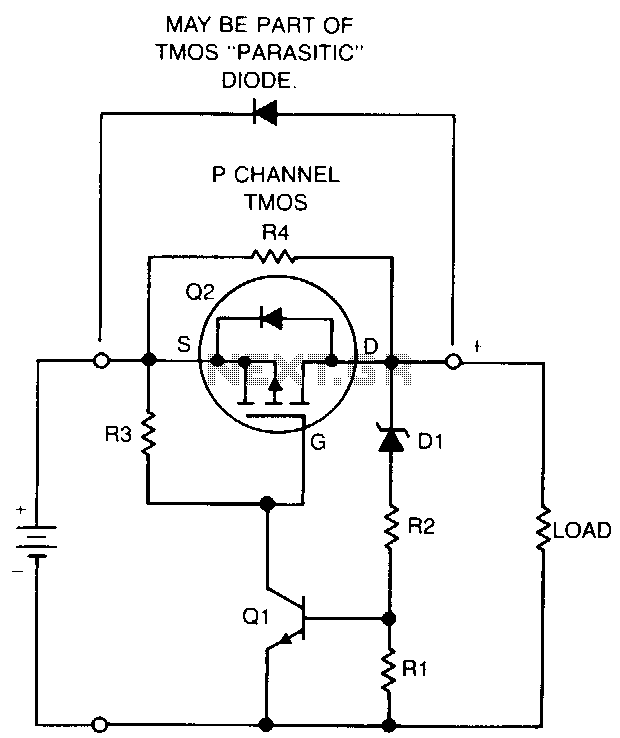
Description: If a NiCad battery is discharged to the point where the lowest capacity cell becomes fully discharged and reverses polarity, that cell will typically short internally and become unusable. To prevent this type of damage, this circuit detects a one-cell drop of 1.25 V and disconnects the load before cell reversal can occur. A low-current zener diode or other voltage sensor (D1) along with resistors (R1 and R2) establishes a reference level for transistor (Q1). These resistors bias the zener to a few microamperes above its "knee." Therefore, if the battery voltage falls by more than 1.25 V, Q1 turns off, which also turns off Q2 and disconnects the load. After the load is disconnected, if the battery returns to nominal voltage, the high value of the resistor shunting Q2 provides sufficient output voltage to reset the voltage sensor and turn Q2 back on. Additionally, a shunt diode (D2) or the parasitic diode of the TMOS device, if suitable, allows the battery to be charged from the load terminals. The protection circuit presents a shunt current of only 10 mA at nominal battery voltage, which is low compared to the internal leakage of the batteries.
This circuit serves as a protective measure for NiCad batteries, preventing irreversible damage due to cell reversal. The primary function is based on sensing the voltage drop across the cells. The zener diode (D1) is critical in establishing a reference voltage. When the voltage across the battery falls below the set threshold of 1.25 V, the zener diode conducts, which triggers the transistor (Q1) to turn off. This action results in the transistor (Q2) also being turned off, effectively disconnecting the load from the battery.
Resistors R1 and R2 are strategically chosen to provide a bias current to the zener diode, ensuring it operates just above its knee voltage, which enhances the sensitivity of the voltage detection. The design allows for a minimal shunt current of 10 mA at nominal voltage, ensuring that the circuit does not significantly affect the battery's overall performance or contribute to excessive leakage.
Once the load is disconnected, the circuit is designed to allow the battery to recover. If the battery voltage rises back to its nominal level, the high-value resistor that shunts Q2 ensures that the voltage sensor is reset, allowing Q2 to turn back on and reconnect the load. This feature is crucial for maintaining usability of the battery after a discharge event without requiring manual intervention.
The inclusion of a shunt diode (D2) or utilizing the parasitic diode of a TMOS device provides an additional function, allowing for the possibility of charging the battery from the load terminals, which can be beneficial in certain applications where the load may also serve as a power source. Overall, this circuit design ensures the longevity and reliability of NiCad batteries by preventing conditions that lead to cell reversal and damage.If a NiCad battery is discharged to a point at which the lowest capacity cell becomes fully discharged and reverses polarity, that cell will usually short internally and become unusable. To prevent this type of damage, this circuit detects a one-cell drop of 1.25 V and turns the load off before cell reversal can occur.
Low-current zener or other voltage sensor Dl and resistors Rl and R2 establish a reference level for transistor Ql. These resistors bias the zener to a few microamperes above its "knee." Therefore, if battery voltage falls more than 1.25 V, Ql turns off, turning off Q2, and disconnecting the load. After the load is disconnected, if the battery returns to nominal voltage, the high value of resistor shunting Q2 provides enough output voltage to reset the voltage sensor and turn Q2 back on.
If desirable, shunt diode D2 or the parasitic diode of the TMOS device, if suitable, allows the battery to be charged from the load terminals. The protection circuit presents a shunt current of only 10 mA at nominal battery voltage, which is low relative to the internal leakage of the batteries.
This circuit serves as a protective measure for NiCad batteries, preventing irreversible damage due to cell reversal. The primary function is based on sensing the voltage drop across the cells. The zener diode (D1) is critical in establishing a reference voltage. When the voltage across the battery falls below the set threshold of 1.25 V, the zener diode conducts, which triggers the transistor (Q1) to turn off. This action results in the transistor (Q2) also being turned off, effectively disconnecting the load from the battery.
Resistors R1 and R2 are strategically chosen to provide a bias current to the zener diode, ensuring it operates just above its knee voltage, which enhances the sensitivity of the voltage detection. The design allows for a minimal shunt current of 10 mA at nominal voltage, ensuring that the circuit does not significantly affect the battery's overall performance or contribute to excessive leakage.
Once the load is disconnected, the circuit is designed to allow the battery to recover. If the battery voltage rises back to its nominal level, the high-value resistor that shunts Q2 ensures that the voltage sensor is reset, allowing Q2 to turn back on and reconnect the load. This feature is crucial for maintaining usability of the battery after a discharge event without requiring manual intervention.
The inclusion of a shunt diode (D2) or utilizing the parasitic diode of a TMOS device provides an additional function, allowing for the possibility of charging the battery from the load terminals, which can be beneficial in certain applications where the load may also serve as a power source. Overall, this circuit design ensures the longevity and reliability of NiCad batteries by preventing conditions that lead to cell reversal and damage.If a NiCad battery is discharged to a point at which the lowest capacity cell becomes fully discharged and reverses polarity, that cell will usually short internally and become unusable. To prevent this type of damage, this circuit detects a one-cell drop of 1.25 V and turns the load off before cell reversal can occur.
Low-current zener or other voltage sensor Dl and resistors Rl and R2 establish a reference level for transistor Ql. These resistors bias the zener to a few microamperes above its "knee." Therefore, if battery voltage falls more than 1.25 V, Ql turns off, turning off Q2, and disconnecting the load. After the load is disconnected, if the battery returns to nominal voltage, the high value of resistor shunting Q2 provides enough output voltage to reset the voltage sensor and turn Q2 back on.
If desirable, shunt diode D2 or the parasitic diode of the TMOS device, if suitable, allows the battery to be charged from the load terminals. The protection circuit presents a shunt current of only 10 mA at nominal battery voltage, which is low relative to the internal leakage of the batteries.
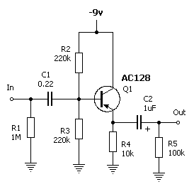
Leaky Transistor Buffer
The wah pedal operates before the amplifier but produces a low volume and a scratchy sound when the pedal is rocked back and forth. It functions correctly without the buffer. When placed in front of a Fuzz Face, no sound...

Transistor Pulse Generator
Seven narrow pulses ranging from 2 Hz to 50 kHz are generated by this circuit. Capacitors C1 through C4 provide frequency ranges in decode steps. Resistors R1 and R2 regulate the charging time of capacitors C1 through C4. R2 is...
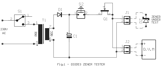
diode zener tester
Frequently, there are situations where the need arises to utilize a Zener diode, yet the operational voltage is unknown. Often, the characteristics or type inscribed on the diode are not legible.
Zener diodes are essential components in electronic circuits, primarily used...
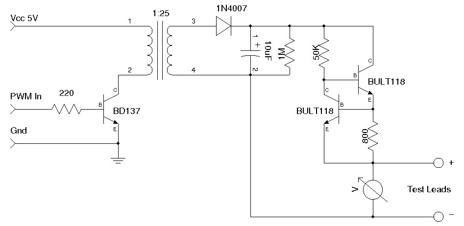
Simple Zener Diode Tester
A simple Zener diode tester circuit, when combined with a PWM generator, can be utilized to measure the breakdown voltage of Zener diodes. More generally, it can also measure the breakdown voltages (e.g., BVceo, BVcbo) of BJTs (Bipolar Junction Transistors)....
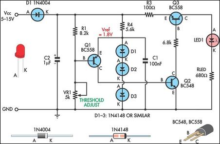
Low Supply Rail Detection
This is a simple low supply rail detection circuit that is inexpensive and can be assembled in approximately 20 minutes. It operates with low power consumption, making it suitable for integration into battery-powered devices. The circuit utilizes three low-cost transistors...
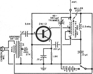
Transistor Circuits
It had been a little over a decade since the invention of the transistor when this article appeared in the August 1959 edition of Popular Electronics. Transistors were still a mystery to many, including engineers, technicians, and hobbyists. Author James...
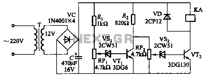
Mains undervoltage overvoltage protection circuit
The circuit employs a transistor control mechanism. When the grid voltage is within the normal range, relay KA is activated, supplying power to the load. If the grid voltage falls below the minimum allowable threshold (adjustable via potentiometer RPz) or...
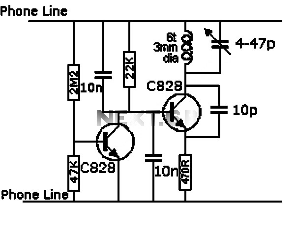
Low Capacitance High Impedance Amplifier Circuit Using Transistor
This series-feedback configuration of components provides a high input impedance and stable, wide-band gain video amplifier suitable for general-purpose applications. Below is the schematic representation of the circuit.
The described video amplifier circuit employs a series-feedback topology, which is instrumental in...
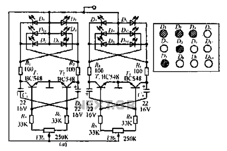
An adjustable bounce lighting circuit
A circuit involving oscillations is composed of a Houle Wang oscillator that utilizes a transistor configuration with components labeled Ti, n, and n, along with a composition of Q constants for the cycle. The waveform can be modified by changing...