


nicad battery charger uses
#NiCad
#constant current
#voltage cutoff
#audible alarm
#transformer
#rectifier diodes
#filter capacitor
#voltage regulator
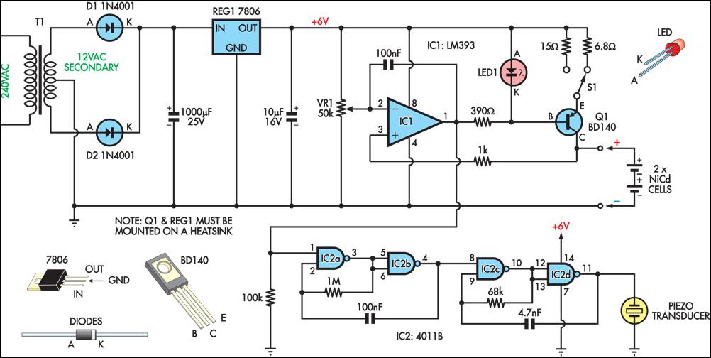
Description: This circuit charges two NiCad cells with a constant current and features dual charging rates, voltage cutoff, and an audible alarm. The circuit is powered by a 12VAC center-tapped mains transformer, along with two rectifier diodes (D1 & D2) and a 1000µF filter capacitor. A 7806 three-terminal regulator generates a 6V rail for the remainder of the circuit. Transistor Q1 and LED1 form a basic constant-current source. The forward voltage of the red LED (approximately 1.5V) minus Q1's base-emitter voltage (approximately 0.6V) appears across either a 6.8Ω or a 15Ω emitter resistor, depending on the position of switch S1. With a 15Ω resistance in the emitter circuit, the charging current is about 60mA, while with a 6.8Ω resistance, it is approximately 130mA. This current is sufficient to charge 600mAh "AA" cells in 14 hours and five hours, respectively. An LM393 voltage comparator (IC1) is employed for the voltage cutoff function. Its inverting input is set to 2.9V (nominal) via trimpot VR1, while the non-inverting input monitors the battery voltage. During charging, the output transistor of the LM393 is activated, which turns on Q1 and enables the current source. Once the cells reach approximately 80% of their capacity, their terminal voltages will exceed 1.45V, causing the voltage at the non-inverting input (pin 3) of IC1 to surpass the reference voltage on the inverting input (pin 2). This results in the output of IC1 switching off, which in turn deactivates Q1 and disables the current source. To prevent rapid switching around the voltage cutoff threshold, a 100nF capacitor provides feedback between the output and inverting input of the comparator. Additionally, four NAND gates are utilized to construct two simple oscillators of different frequencies. When cascaded, these oscillators produce a pulsed tone from the piezo transducer, indicating charge completion. It is crucial to note that absolute terminal voltage may not always reliably indicate the charge state of NiCad batteries. Batteries should not be charged beyond the manufacturer's specified duration.
The circuit design is centered around a dual charging system, allowing for flexibility in charging rates suited for different battery conditions. The incorporation of a 12VAC center-tapped transformer ensures that the circuit can effectively convert AC voltage to a usable DC voltage through the rectification process, with the rectifier diodes D1 and D2 playing a vital role in this conversion. The 1000µF filter capacitor smooths out the rectified voltage, providing a stable input for the voltage regulator.
The 7806 voltage regulator is critical in maintaining a consistent 6V output, which is essential for the proper operation of the constant current source formed by Q1 and LED1. The choice of using a red LED in conjunction with Q1 serves a dual purpose: it not only provides visual feedback but also plays a role in establishing the required voltage drop for the constant current operation.
The variable resistor VR1 allows for fine-tuning of the cutoff voltage, ensuring that the circuit can be adjusted to accommodate variations in battery chemistry or capacity. The LM393 comparator is an effective choice for monitoring the battery voltage, providing a reliable means of determining when to cease charging, thus preventing overcharging and potential battery damage.
The integration of the NAND gates to create oscillators adds an auditory feedback mechanism, which is crucial for user awareness regarding the charging status. The pulsed tone from the piezo transducer serves as an alert that the charging process is complete, enhancing user interaction with the device.
Overall, this circuit exemplifies a well-thought-out design that prioritizes safety and efficiency in charging NiCad batteries, with multiple features that enhance functionality and user experience.This circuit charges two NiCad cells with a constant current and features dual charging rates, voltage cutoff and an audible alarm. The circuit is powered by a 12VAC centre-tapped mains transformer, together with two rectifier diodes (D1 & D2) and a 1000mF filter capacitor.
A 7806 3-terminal regulator is used to generate a 6V rail for the remainde r of the circuit. Transistor Q1 and LED1 constitute a basic constant-current source. The forward voltage of the red LED (about 1. 5V) minus Q1`s base-emitter voltage (about 0. 6V) appears across the 6. 8W or 15W emitter resistors, depending on the position of S1. With a 15W resistance in the emitter circuit, the charging current is about 60mA, whereas with 6. 8W it is about 130mA. This is sufficient to charge 600mAH "AA" cells in 14 hours and five hours, respectively. An LM393 voltage comparator (IC1) is used for the voltage cutoff function. Its inverting input is set to 2. 9V (nominal) via trimpot VR1, while the non-inverting input senses battery voltage. This means that while the cells are being charged, the output transistor (in the LM393) is switched on, also switching on Q1 and enabling the current source. Once the cells are charged to approximately 80% or more of capacity, their terminal voltages will exceed 1.
45V, so the voltage at the non-inverting input (pin 3) of IC1 will exceed the reference voltage on the inverting input (pin 2). This causes IC1`s output to switch off, in turn switching Q1 off and disabling the current source. To prevent rapid switching action around the voltage cutoff point, a 100nF capacitor provides feedback between the output and inverting input of the comparator.
Four NAND gates are used to build two simple oscillators of different frequencies. When cascaded together, the result is a pulsed tone from the piezo transducer to indicate charge completion. Absolute terminal voltage is not always a reliable indicator of Nicad battery charge state. Importantly, batteries should never be charged for longer than the manufacturer`s specified period.
The circuit design is centered around a dual charging system, allowing for flexibility in charging rates suited for different battery conditions. The incorporation of a 12VAC center-tapped transformer ensures that the circuit can effectively convert AC voltage to a usable DC voltage through the rectification process, with the rectifier diodes D1 and D2 playing a vital role in this conversion. The 1000µF filter capacitor smooths out the rectified voltage, providing a stable input for the voltage regulator.
The 7806 voltage regulator is critical in maintaining a consistent 6V output, which is essential for the proper operation of the constant current source formed by Q1 and LED1. The choice of using a red LED in conjunction with Q1 serves a dual purpose: it not only provides visual feedback but also plays a role in establishing the required voltage drop for the constant current operation.
The variable resistor VR1 allows for fine-tuning of the cutoff voltage, ensuring that the circuit can be adjusted to accommodate variations in battery chemistry or capacity. The LM393 comparator is an effective choice for monitoring the battery voltage, providing a reliable means of determining when to cease charging, thus preventing overcharging and potential battery damage.
The integration of the NAND gates to create oscillators adds an auditory feedback mechanism, which is crucial for user awareness regarding the charging status. The pulsed tone from the piezo transducer serves as an alert that the charging process is complete, enhancing user interaction with the device.
Overall, this circuit exemplifies a well-thought-out design that prioritizes safety and efficiency in charging NiCad batteries, with multiple features that enhance functionality and user experience.This circuit charges two NiCad cells with a constant current and features dual charging rates, voltage cutoff and an audible alarm. The circuit is powered by a 12VAC centre-tapped mains transformer, together with two rectifier diodes (D1 & D2) and a 1000mF filter capacitor.
A 7806 3-terminal regulator is used to generate a 6V rail for the remainde r of the circuit. Transistor Q1 and LED1 constitute a basic constant-current source. The forward voltage of the red LED (about 1. 5V) minus Q1`s base-emitter voltage (about 0. 6V) appears across the 6. 8W or 15W emitter resistors, depending on the position of S1. With a 15W resistance in the emitter circuit, the charging current is about 60mA, whereas with 6. 8W it is about 130mA. This is sufficient to charge 600mAH "AA" cells in 14 hours and five hours, respectively. An LM393 voltage comparator (IC1) is used for the voltage cutoff function. Its inverting input is set to 2. 9V (nominal) via trimpot VR1, while the non-inverting input senses battery voltage. This means that while the cells are being charged, the output transistor (in the LM393) is switched on, also switching on Q1 and enabling the current source. Once the cells are charged to approximately 80% or more of capacity, their terminal voltages will exceed 1.
45V, so the voltage at the non-inverting input (pin 3) of IC1 will exceed the reference voltage on the inverting input (pin 2). This causes IC1`s output to switch off, in turn switching Q1 off and disabling the current source. To prevent rapid switching action around the voltage cutoff point, a 100nF capacitor provides feedback between the output and inverting input of the comparator.
Four NAND gates are used to build two simple oscillators of different frequencies. When cascaded together, the result is a pulsed tone from the piezo transducer to indicate charge completion. Absolute terminal voltage is not always a reliable indicator of Nicad battery charge state. Importantly, batteries should never be charged for longer than the manufacturer`s specified period.
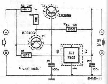
5 volts high current power supply using 7805 voltage regulator
This power supply circuit is designed to provide a high current 5-volt output using a 7805 voltage regulator along with several standard electronic components. The transistor T1 functions as a current limiter. When the voltage across resistors R2 and R3...
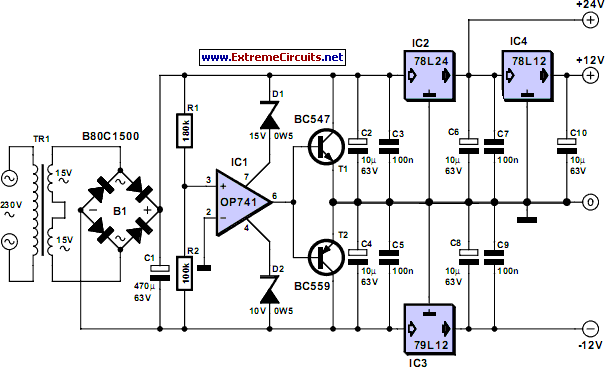
Triple Power Supply
Inexpensive miniature transformers typically provide one or two secondary voltages, which are sufficient for generating a set of positive and negative supply voltages, as required for operational amplifier circuits. However, if an additional voltage higher than either of the supply...
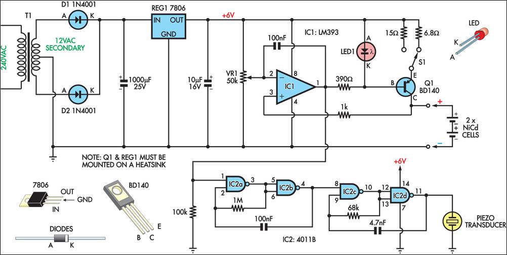
Nicad Charger Uses Voltage Cut-Out
This circuit charges two NiCad cells with a constant current and features dual charging rates, voltage cutoff, and an audible alarm. The circuit is powered by a 12VAC center-tapped mains transformer, along with two rectifier diodes (D1 & D2) and...
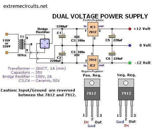
Dual Voltage 12V Power Supply
The following circuit diagram of a dual voltage power supply can be used for miscellaneous applications. It requires a few components to build. The most important components of this circuit are regulators: 1: (AN) 7812 and 2: (AN) 7912. AN7812...
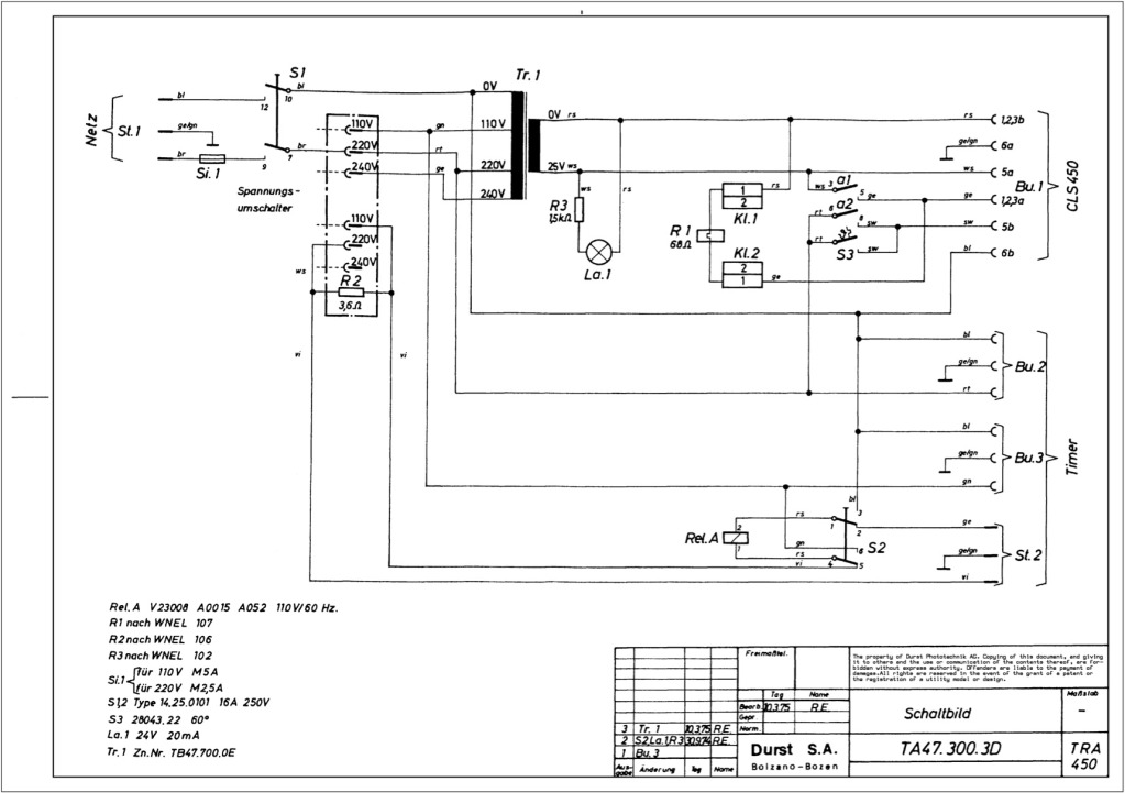
Durst power supplies EST 301 and EST 450
The regulator board of the ES301 has been inspected, revealing that the PCB contacts of the current sensing resistors R42 and R43 are severely burned. There is a nearby group of resistors that also need to be replaced, but their...
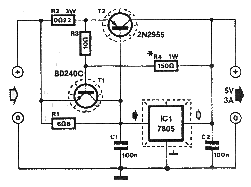
Shortcircuit protected voltage regulator
At this voltage regulator prototype the maximum current, with output shortcircuited it was only 0.5 A, so no overheating occurred. In this DC voltage regulator circuit, T1 is for current limitation. As soon as the voltage on the R2 +...
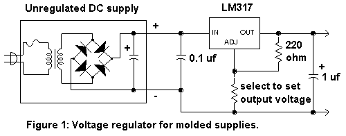
Regulator Combination Circuits
There are a number of ways to obtain the low voltages required to run small projects from the wall power outlet. The simplest way is to buy a factory-built molded supply which is designed to plug directly into the wall...
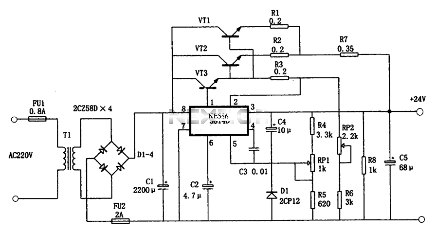
5G14D + 24V 1.9A power supply
The circuit illustrated in the figure is a +24V, 1.9A power supply design. It employs the 5G14D domestic integrated voltage regulator as the core component, supported by three external power transistors. While the 5G14D voltage regulator has a rated current...
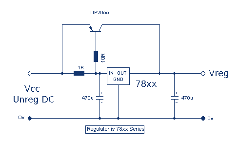
Increasing Regulator Current
Although the 78xx series of voltage regulators are available with different current outputs, you can boost the available current output with this circuit. A power transistor is used to supply extra current to the load, maintaining a constant voltage. Currents...