


NiCd Simple Smart Nicad Battery Charger circuit
#NiCd
#rechargeable battery
#constant current
#battery charger
#polarity protection
#Q2 transistor
#aerial current
#NiMH
#Lithium battery
#smart charger
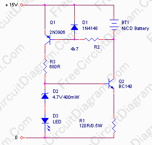
Description: In appliances that require alternating current, NiCad (NiCd) rechargeable batteries still demonstrate significant performance advantages compared to NiMH and lithium batteries. The charger circuit is critical in handling incorrect polarity of the battery placement. The core of this battery charger circuit is Q2, which is configured as a constant current source for the battery. LED D3 and zener diode D2 ensure that the voltage applied to the base of Q2 remains constant, resulting in a steady voltage and current across R1. With the values indicated in the schematic diagram, the current flowing through R1 will be approximately 50 mA. The base of Q2 is supplied by R3, which is controlled by Q1. The base of Q1 is regulated by the battery voltage, preventing Q1 from operating if the battery is connected with incorrect polarity. It is important to note that while this battery charger can charge four NiCad batteries in series, it cannot detect if one battery is connected with incorrect polarity while two or three other batteries are correctly connected. A small transformer, a bridge rectifier, and an electrolytic capacitor are required to power this circuit. Adequate heat sinking for Q2 is essential. This circuit will function as long as the battery is not completely discharged, as a minimal voltage is necessary to activate the Q1 transistor.
The described NiCad battery charger circuit is designed to provide a reliable charging solution for NiCd batteries, which are commonly used in various applications due to their robustness. The circuit utilizes a constant current source configuration, which is essential for maintaining a steady charging current that prevents overcharging and damage to the batteries. Q2, as the main control element, regulates the charging current based on the feedback received from R1, ensuring that the current remains at approximately 50 mA, which is suitable for NiCd batteries.
The inclusion of LED D3 serves a dual purpose: it indicates the operational status of the charger and provides visual feedback that charging is in progress. The zener diode D2 plays a critical role in stabilizing the voltage at the base of Q2, ensuring that fluctuations in input voltage do not affect the charging current. This stability is crucial for the longevity of the batteries being charged.
The circuit’s ability to handle incorrect polarity is facilitated by the transistor Q1, which acts as a protective switch. If the battery is connected in reverse, the voltage at the base of Q1 will not be sufficient to turn it on, effectively preventing any current from flowing through Q2 and protecting the batteries from potential damage. However, it is important to note that while the circuit can charge multiple batteries in series, it lacks the capability to detect a single battery connected in reverse when other batteries are correctly oriented. This limitation necessitates careful attention during battery installation.
Powering the circuit requires a small transformer to step down the mains voltage, followed by a bridge rectifier to convert the alternating current to direct current, which is then filtered by an electrolytic capacitor to provide a smooth DC voltage for the charger operation. The design emphasizes the need for proper thermal management, hence the recommendation for a heat sink for Q2, as excessive heat can lead to component failure and reduced efficiency.
In summary, this NiCad battery charger circuit is an effective solution for charging NiCd batteries, combining essential features such as constant current regulation, polarity protection, and visual indicators, while also highlighting the importance of careful battery placement and thermal management.In appliance that appeal for aerial current, Nicad (NiCd) rechargeable array still has the angry achievement compared to NiMH and Lithium battery. The charger ambit actuality is acute in the way it handle the amiss polarity of the array placement. The core of this battery charger circuit is the Q2, configured a constant current source for the batt
ery. LED D3 and zener diode D2 make the voltage applied to Q2 base constant, therefore the voltage and the current across R1 is constant. Using the value shown in the schematic diagram, the current flow through R1 will be constant at around 50 mA.
You can see that the base of Q2 is supplied by R3, which is controlled by Q1. Look at the Q1 base, it`s controlled by the battery voltage, so Q1 won`t works if the battery is placed in wrong polarity. Just note that although this battery charger could charge four Nicad battery (in series), it can`t detect if one battery placed in wrong polarity while two or three other batteries are in right polarity.
A small transformer, a bridge diode, and an electrolytic capacitor is needed to supply this circuit. Remember to provide a sufficient heat sink for Q2. This circuit will work as long as the battery is not completely discharged, because its weak voltage is needed to trigger the Q1 transistor.
The described NiCad battery charger circuit is designed to provide a reliable charging solution for NiCd batteries, which are commonly used in various applications due to their robustness. The circuit utilizes a constant current source configuration, which is essential for maintaining a steady charging current that prevents overcharging and damage to the batteries. Q2, as the main control element, regulates the charging current based on the feedback received from R1, ensuring that the current remains at approximately 50 mA, which is suitable for NiCd batteries.
The inclusion of LED D3 serves a dual purpose: it indicates the operational status of the charger and provides visual feedback that charging is in progress. The zener diode D2 plays a critical role in stabilizing the voltage at the base of Q2, ensuring that fluctuations in input voltage do not affect the charging current. This stability is crucial for the longevity of the batteries being charged.
The circuit’s ability to handle incorrect polarity is facilitated by the transistor Q1, which acts as a protective switch. If the battery is connected in reverse, the voltage at the base of Q1 will not be sufficient to turn it on, effectively preventing any current from flowing through Q2 and protecting the batteries from potential damage. However, it is important to note that while the circuit can charge multiple batteries in series, it lacks the capability to detect a single battery connected in reverse when other batteries are correctly oriented. This limitation necessitates careful attention during battery installation.
Powering the circuit requires a small transformer to step down the mains voltage, followed by a bridge rectifier to convert the alternating current to direct current, which is then filtered by an electrolytic capacitor to provide a smooth DC voltage for the charger operation. The design emphasizes the need for proper thermal management, hence the recommendation for a heat sink for Q2, as excessive heat can lead to component failure and reduced efficiency.
In summary, this NiCad battery charger circuit is an effective solution for charging NiCd batteries, combining essential features such as constant current regulation, polarity protection, and visual indicators, while also highlighting the importance of careful battery placement and thermal management.In appliance that appeal for aerial current, Nicad (NiCd) rechargeable array still has the angry achievement compared to NiMH and Lithium battery. The charger ambit actuality is acute in the way it handle the amiss polarity of the array placement. The core of this battery charger circuit is the Q2, configured a constant current source for the batt
ery. LED D3 and zener diode D2 make the voltage applied to Q2 base constant, therefore the voltage and the current across R1 is constant. Using the value shown in the schematic diagram, the current flow through R1 will be constant at around 50 mA.
You can see that the base of Q2 is supplied by R3, which is controlled by Q1. Look at the Q1 base, it`s controlled by the battery voltage, so Q1 won`t works if the battery is placed in wrong polarity. Just note that although this battery charger could charge four Nicad battery (in series), it can`t detect if one battery placed in wrong polarity while two or three other batteries are in right polarity.
A small transformer, a bridge diode, and an electrolytic capacitor is needed to supply this circuit. Remember to provide a sufficient heat sink for Q2. This circuit will work as long as the battery is not completely discharged, because its weak voltage is needed to trigger the Q1 transistor.
battery charger circuits
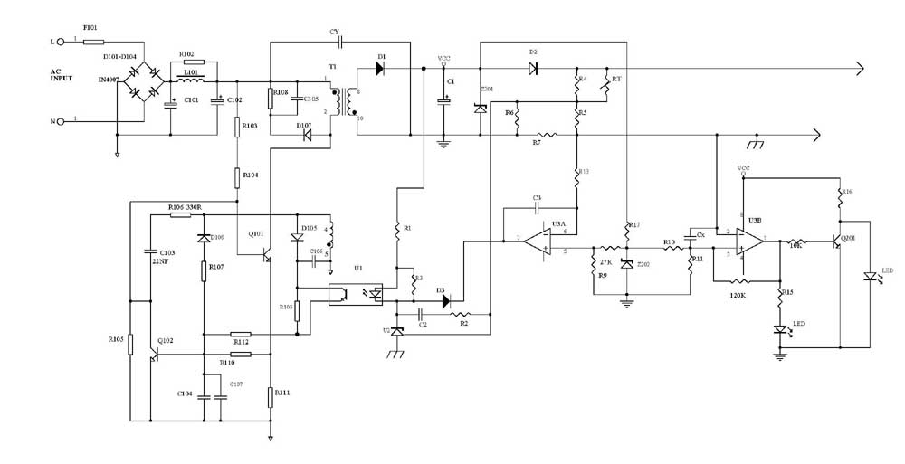
Several schematic drawings of battery charger circuits are provided. These circuits cover 5W to 200W for NiCd, NiMH, Lead-Acid, Li-Ion/Polymer, and LiFePO4 battery packs. The charger circuit files aim to assist users in selecting the appropriate chargers and to enhance...
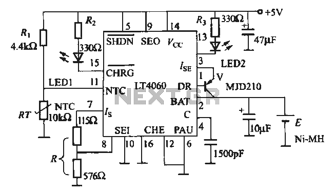
LT4060 with temperature-controlled 2A NiMH battery charger
The charging circuit is designed for rechargeable batteries, particularly for situations where high charging currents can lead to increased temperatures. The LTC4060 includes an external thermistor that detects the charging temperature to prevent overheating. This device operates as a temperature-controlled...
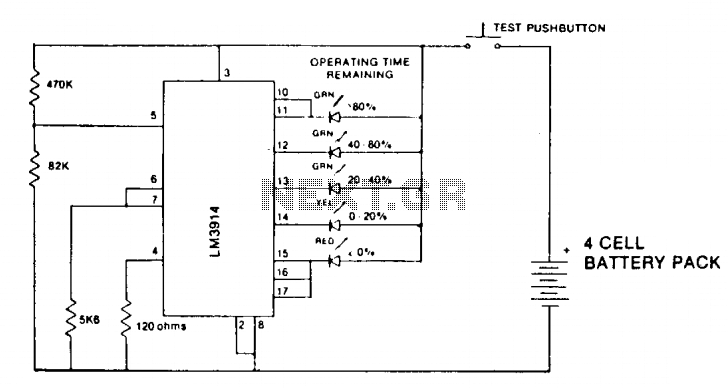
Lithium battery indicator
A state-of-charge indication of a sloping-voltage discharge can be utilized as a state-of-charge indicator. A typical voltage comparator circuit that provides a visual indication of the state of charge is presented. Components identified are for a 4-cell input voltage ranging...
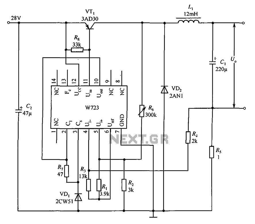
Switching the constant current source consisting of the application circuit W723
The Multiport W723 is an adjustable constant current regulator designed for use in switching regulator circuits, capable of delivering an output current of 1A. In the illustrated circuit, the W723 reference base voltage is approximately 7.2V. This voltage is divided...

Simple Battery Charger Circuit Charges Upto 12 NiCD Cells
This circuit is designed to charge between one and twelve NiCd cells using a car battery. With switch S1 set to the normal position, it is capable of charging up to six cells.
The circuit operates by utilizing a car battery...
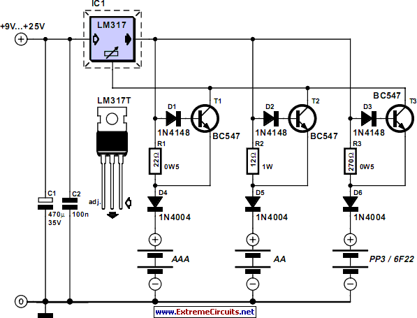
Switchless NiCd-NiMH Battery Charger
This circuit can be utilized as a replacement for the single current limiting resistor commonly found in inexpensive battery chargers. The alternative presented here will eventually...
This circuit serves as an improved solution for current limiting in battery chargers, particularly those...
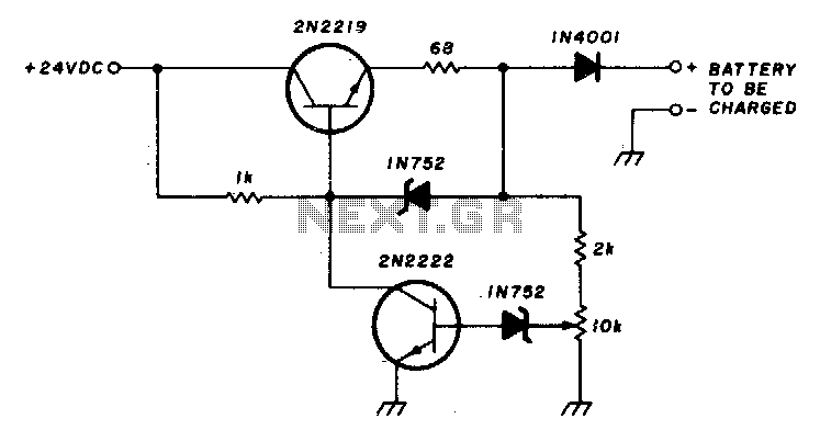
200Ma-12v ni-cad battery charger
This circuit charges a battery at a rate of 75 mA, allowing the battery to remain in the charger indefinitely until fully charged. Once the battery reaches its full charge, the circuit reduces the current to a trickle rate. To...
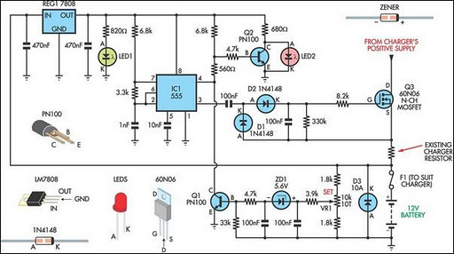
Battery Charger Regulator
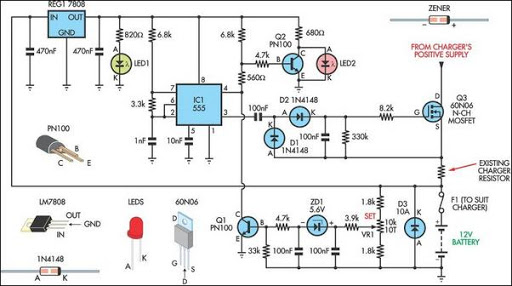
Most commercial car battery chargers cannot be left connected to the battery for extended periods, as this can lead to overcharging and subsequent battery damage. This add-on circuit is connected in series with the battery being charged and is powered...
Battery Charger Regulator
Most off-the-shelf car battery chargers cannot be left connected to the battery for long periods of time as overcharging can cause battery damage.
The operation of car battery chargers typically involves converting alternating current (AC) from a wall outlet into direct...