


PIC16F84 Solar Charger
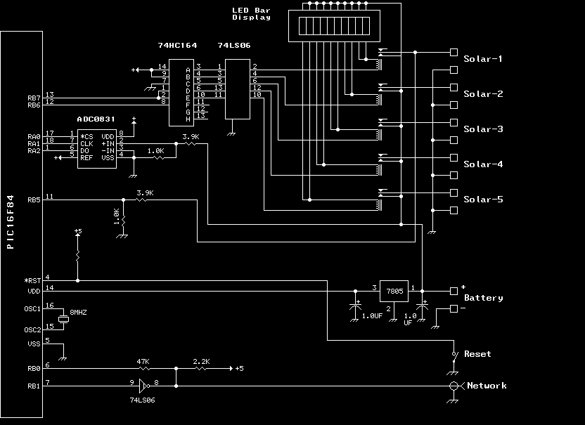
Description: The previous version of this device used pulse width modulation (PWM) to control the power from the five solar panels to charge the battery bank. Under full sun conditions, the MOSFETs got a bit warm and the whole unit radiated a lot of RFI. This design uses a set of relays - one for each panel. If the controller decides the battery voltage is too low, it engages another relay; if it's too high, it drops one out. This tends to 'float' the voltage at about 14 volts as long as sufficient sunlight is available. More: The controller also implements a network style interface (open collector TTL, 9600 baud). This makes it possible to 'tweak' the charge settings using a terminal program and an RS-232 to TTL interface (coming to this website soon). If you choose to duplicate this device, you may leave out the network stuff and 'hardwire' the charge settings in software.
The circuit described operates as a solar charge controller, designed to optimize battery charging from five solar panels while mitigating issues related to heat generation and radio frequency interference (RFI). The previous iteration utilized pulse width modulation (PWM) for power regulation, which led to excessive heating of the MOSFETs and unwanted RFI emissions. The current design employs a relay-based system, where each solar panel is connected to a dedicated relay. This relay configuration allows for more efficient management of the solar input based on the battery's voltage level.
The controller continuously monitors the battery voltage. If the voltage falls below a predetermined threshold, the controller activates an additional relay to increase the solar input, facilitating faster charging. Conversely, if the battery voltage exceeds a specified limit, the controller deactivates the relay associated with one of the solar panels, effectively reducing the charging current and maintaining the battery voltage at approximately 14 volts. This floating voltage level ensures that the battery remains in a healthy state of charge without overcharging, provided that adequate sunlight is present.
In addition to its primary function as a charge controller, the circuit also incorporates a network-style interface that operates at 9600 baud using open collector TTL logic. This interface enables users to adjust charge settings remotely via a terminal program, utilizing an RS-232 to TTL converter. This feature provides flexibility for users who wish to customize the performance of the charge controller based on their specific requirements. For those intending to replicate the device, the network functionality can be omitted, and the charge settings can be hardwired into the software, simplifying the design for applications where remote adjustment is unnecessary.
Overall, the combination of relay control and a network interface enhances the functionality and adaptability of the solar charge controller, making it suitable for diverse applications in renewable energy systems.The previous version of this device used pulse width modulation (pwm) to control the power from the five solar panels to charge the battery bank. Under full sun conditions the MOSFETS got a bit warm and the whole unit radiated a lot of RFI. This design uses a set of relays - one for each panel. If the controller decides the battery voltage is too low, it engages another relay; if its too high, it drops one out.
This tends to 'float' the voltage at about 14 volts as long as sufficient sunlight is available. The controller also implements a network style interface (open collector TTL, 9600 baud). This makes it possible to 'tweak' the charge settings using a terminal program and an RS-232 to TTL interface (coming to this web site soon). If you choose to duplicate this device, you may leave out the network stuff and 'hardwire' the charge settings in software.
The circuit described operates as a solar charge controller, designed to optimize battery charging from five solar panels while mitigating issues related to heat generation and radio frequency interference (RFI). The previous iteration utilized pulse width modulation (PWM) for power regulation, which led to excessive heating of the MOSFETs and unwanted RFI emissions. The current design employs a relay-based system, where each solar panel is connected to a dedicated relay. This relay configuration allows for more efficient management of the solar input based on the battery's voltage level.
The controller continuously monitors the battery voltage. If the voltage falls below a predetermined threshold, the controller activates an additional relay to increase the solar input, facilitating faster charging. Conversely, if the battery voltage exceeds a specified limit, the controller deactivates the relay associated with one of the solar panels, effectively reducing the charging current and maintaining the battery voltage at approximately 14 volts. This floating voltage level ensures that the battery remains in a healthy state of charge without overcharging, provided that adequate sunlight is present.
In addition to its primary function as a charge controller, the circuit also incorporates a network-style interface that operates at 9600 baud using open collector TTL logic. This interface enables users to adjust charge settings remotely via a terminal program, utilizing an RS-232 to TTL converter. This feature provides flexibility for users who wish to customize the performance of the charge controller based on their specific requirements. For those intending to replicate the device, the network functionality can be omitted, and the charge settings can be hardwired into the software, simplifying the design for applications where remote adjustment is unnecessary.
Overall, the combination of relay control and a network interface enhances the functionality and adaptability of the solar charge controller, making it suitable for diverse applications in renewable energy systems.The previous version of this device used pulse width modulation (pwm) to control the power from the five solar panels to charge the battery bank. Under full sun conditions the MOSFETS got a bit warm and the whole unit radiated a lot of RFI. This design uses a set of relays - one for each panel. If the controller decides the battery voltage is too low, it engages another relay; if its too high, it drops one out.
This tends to 'float' the voltage at about 14 volts as long as sufficient sunlight is available. The controller also implements a network style interface (open collector TTL, 9600 baud). This makes it possible to 'tweak' the charge settings using a terminal program and an RS-232 to TTL interface (coming to this web site soon). If you choose to duplicate this device, you may leave out the network stuff and 'hardwire' the charge settings in software.
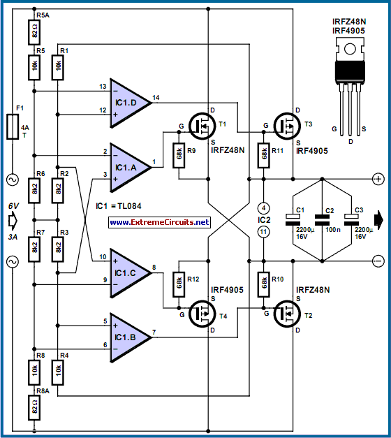
Power MOSFET Bridge Rectifier
The losses in a bridge rectifier can become significant when rectifying low voltages. The voltage drop across the bridge is approximately 1.5 V, which constitutes about 25% loss with an input voltage of 6V. This loss can be reduced by...
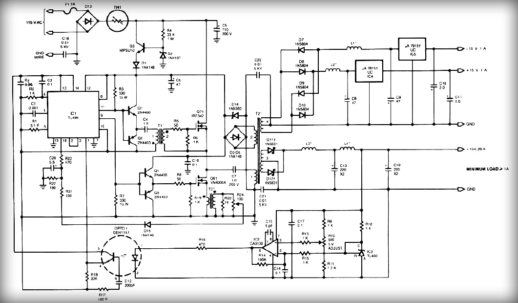
Multiple output switching power supply circuit Schematic Diagram
This power supply employs two VN400A 400-Volt MOSFETs arranged in a half-bridge configuration. The outputs provide +5V at 20A and +15V at 1A. Low-current outputs utilize three-terminal regulators, allowing for either 12 Volts or 15 Volts to be achieved with...
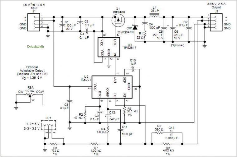
Tl5001 Pulse-width-modulation (pwm) Controller Coupled With A Tps2817 Mosfet Driver
The TLE6282G is an H-Bridge and Half Bridge Driver IC designed for high-current DC brush motor applications in PWM control mode. It is suitable for use in injector and valve applications across 12V, 24V, and 42V power networks. This IC...
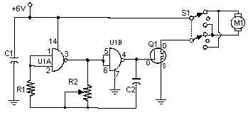
Pulse Width Modulation DC Motor Control
Often, people attempt to control DC motors with a variable resistor or variable resistor connected to a transistor. While the latter approach works well, it generates heat and hence wastes power. This simple pulse width modulation DC motor control eliminates...
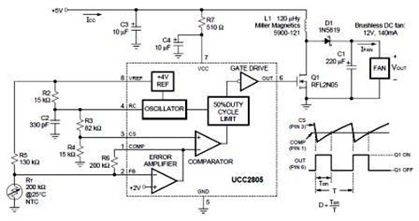
Design of Temperature-Controlled PWM Boost Converter Circuit
A temperature-controlled pulse-width-modulator (PWM) boost converter circuit diagram is illustrated in the following figure. This boost converter is designed to operate a 12V fan using a 5V supply while maintaining temperature control.
The temperature-controlled PWM boost converter circuit operates by stepping...
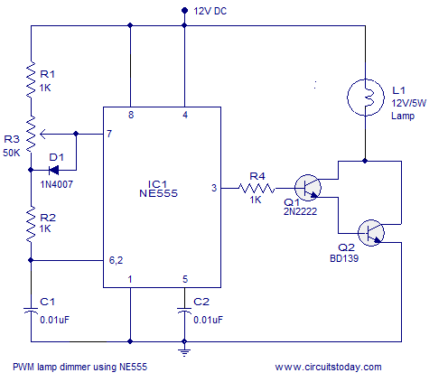
PWM lamp dimmer using NE555 timer IC. Complete circuit diagram and working
A simple PWM lamp dimmer using the NE555 timer IC. The 555 timer IC is configured as a variable duty cycle astable multivibrator to control the brightness of the lamp.
The described circuit utilizes the NE555 timer IC, a versatile and...
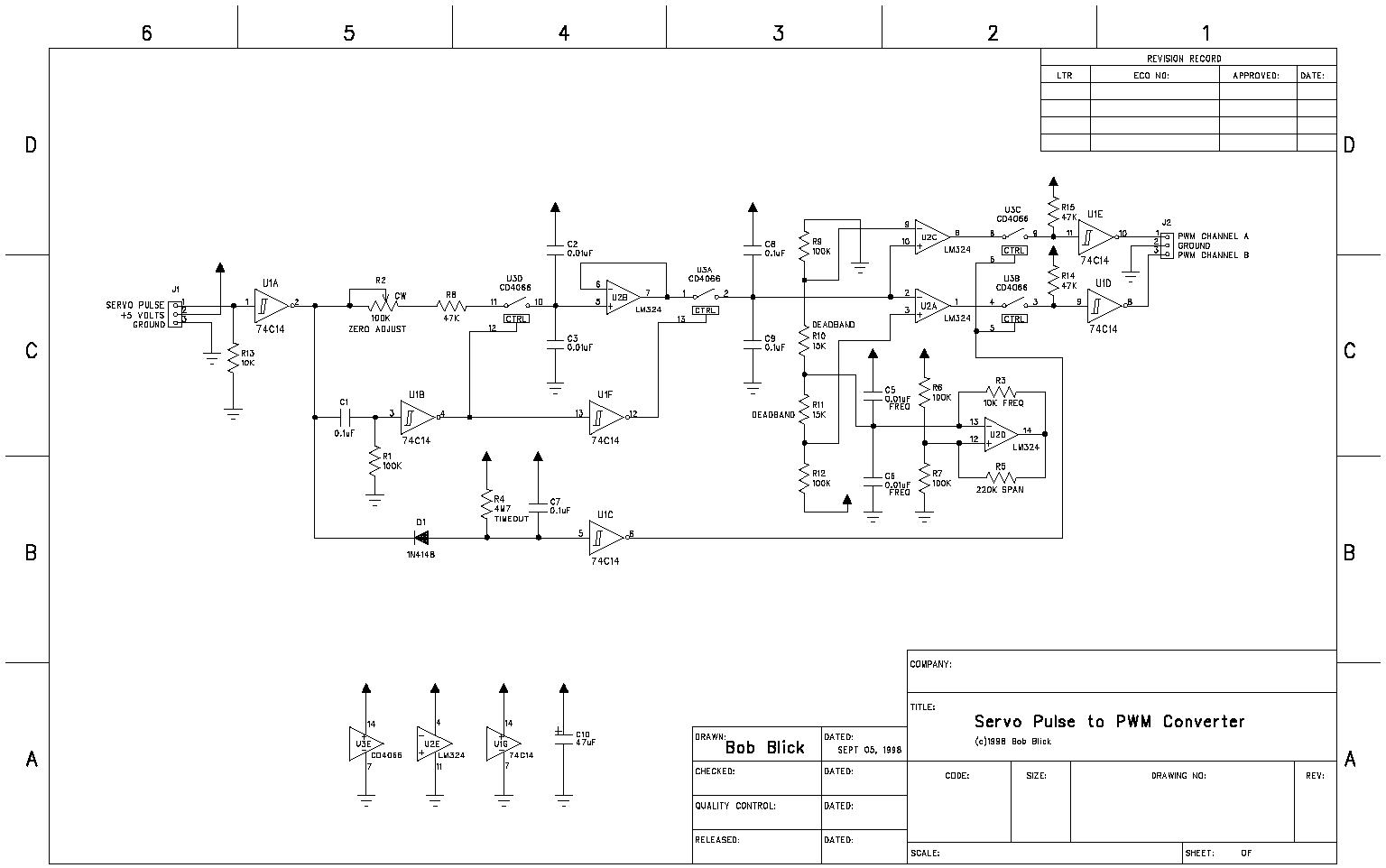
Servo pulse to PWM converter
The circuit presented on this page attempts to be an interface to convert pulses such as provided by a Basic Stamp or R/C receiver to a dual PWM (Pulse Width Modulation) signal required by an H-bridge. The simplest circuit would...
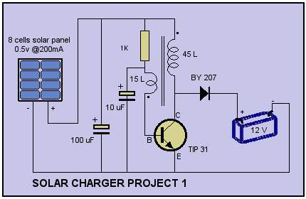
Solar Cell Charger Schematic
Solar Cell Charger Schematic. The circuit was built with a single oscillator system (blocking oscillator).
The solar cell charger schematic utilizes a blocking oscillator configuration to efficiently convert solar energy into electrical energy suitable for charging batteries. This circuit typically comprises...
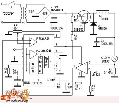
PWM Control Dimming Halogen Lamp
The PWM control dimming circuit for a halogen lamp is illustrated. The halogen lamp operates at a rated voltage of 12V with a nominal power of 20W. This dimmer circuit is capable of adjusting the intensity of the halogen lamp...