


RAPID BATTERY CHARGER FOR ICOM IC 2A
#LM723
#voltage regulator
#constant current
#SCR
#transformer
#rectifier
#filter
#npn transistor
#resistor network
#trickle charge
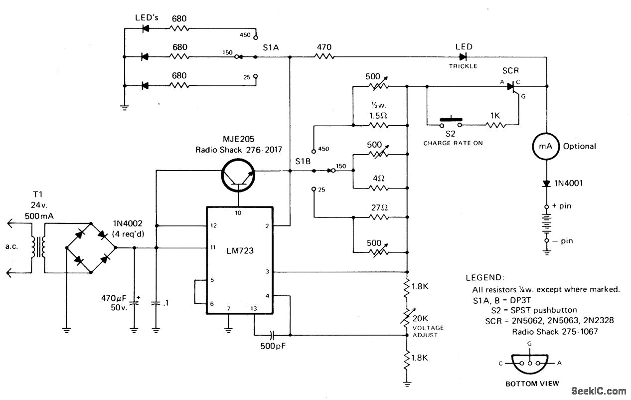
Description: The rectified and filtered voltage from the 24 Vac transformer is applied to the LM723 voltage regulator, along with an NPN pass transistor configured for constant current supply. A 470-ohm resistor limits the trickle current until the momentary pushbutton (S2) is pressed, at which point the SCR activates and current flows through a predetermined resistor network that limits the charging current. The SCR will deactivate when the thermal cutout circuit within the battery pack opens.
The circuit design begins with a 24 Vac transformer, which steps down the voltage to a manageable level suitable for rectification. The output from the transformer is then rectified using a bridge rectifier or a full-wave rectifier configuration, which converts the alternating current (AC) into direct current (DC). The rectified output is smoothed using a filter capacitor to reduce ripple voltage, providing a more stable DC voltage to the next stage.
The LM723 voltage regulator is utilized to maintain a constant output voltage. This adjustable voltage regulator can be set to provide a specific output voltage by configuring external resistors. In this application, it is paired with an NPN pass transistor, which acts as a current amplifier, allowing for higher current output than the LM723 can provide alone. This configuration is particularly useful for applications requiring a stable and regulated power supply for charging batteries.
The inclusion of the 470-ohm resistor plays a critical role in controlling the initial charging current. When the system is powered on, this resistor limits the trickle charge to the connected battery, preventing damage from excessive current. The momentary pushbutton switch (S2) serves as a manual activation mechanism; when pressed, it triggers the silicon-controlled rectifier (SCR) to conduct, allowing a higher charging current to flow through the battery.
The SCR is a key component in this circuit, providing controlled rectification. Once triggered by the pushbutton, it allows current to flow through the resistor network, which has been designed to limit the charging current to a safe level. This network ensures that the battery charges efficiently without overheating.
Safety is further enhanced by the thermal cutout circuit integrated within the battery pack. This circuit monitors the temperature of the battery during charging. If the temperature exceeds a predetermined threshold, the thermal cutout opens, effectively turning off the SCR and halting the charging process. This feature is essential for preventing battery damage and ensuring safe operation.
Overall, this circuit design effectively combines rectification, voltage regulation, and current limiting to provide a reliable charging solution for batteries, with built-in safety mechanisms to protect against overcurrent and overheating conditions.Rectifted and filtered voltage from the 24 Vac transformer is applied to the LM723 voltage regulator and the npn pass transistor set up for constant current supply. The 470 ohm resistor limits trickle current until the momentary pushbutton (S2) is depressed, the SCR turns on and current ftows through the previously determined resistor network limi
ting the charging current. The SCR will turn off when the thennal cutout circuit inside the battery pack opens up.
The circuit design begins with a 24 Vac transformer, which steps down the voltage to a manageable level suitable for rectification. The output from the transformer is then rectified using a bridge rectifier or a full-wave rectifier configuration, which converts the alternating current (AC) into direct current (DC). The rectified output is smoothed using a filter capacitor to reduce ripple voltage, providing a more stable DC voltage to the next stage.
The LM723 voltage regulator is utilized to maintain a constant output voltage. This adjustable voltage regulator can be set to provide a specific output voltage by configuring external resistors. In this application, it is paired with an NPN pass transistor, which acts as a current amplifier, allowing for higher current output than the LM723 can provide alone. This configuration is particularly useful for applications requiring a stable and regulated power supply for charging batteries.
The inclusion of the 470-ohm resistor plays a critical role in controlling the initial charging current. When the system is powered on, this resistor limits the trickle charge to the connected battery, preventing damage from excessive current. The momentary pushbutton switch (S2) serves as a manual activation mechanism; when pressed, it triggers the silicon-controlled rectifier (SCR) to conduct, allowing a higher charging current to flow through the battery.
The SCR is a key component in this circuit, providing controlled rectification. Once triggered by the pushbutton, it allows current to flow through the resistor network, which has been designed to limit the charging current to a safe level. This network ensures that the battery charges efficiently without overheating.
Safety is further enhanced by the thermal cutout circuit integrated within the battery pack. This circuit monitors the temperature of the battery during charging. If the temperature exceeds a predetermined threshold, the thermal cutout opens, effectively turning off the SCR and halting the charging process. This feature is essential for preventing battery damage and ensuring safe operation.
Overall, this circuit design effectively combines rectification, voltage regulation, and current limiting to provide a reliable charging solution for batteries, with built-in safety mechanisms to protect against overcurrent and overheating conditions.Rectifted and filtered voltage from the 24 Vac transformer is applied to the LM723 voltage regulator and the npn pass transistor set up for constant current supply. The 470 ohm resistor limits trickle current until the momentary pushbutton (S2) is depressed, the SCR turns on and current ftows through the previously determined resistor network limi
ting the charging current. The SCR will turn off when the thennal cutout circuit inside the battery pack opens up.

thrifty voltage regulator
One of the drawbacks of a three-pin voltage regulator is that the input voltage needs to be 2.5 to 3 V higher than the output voltage. This makes these integrated regulators unsuitable for battery power supplies. For instance, if the...
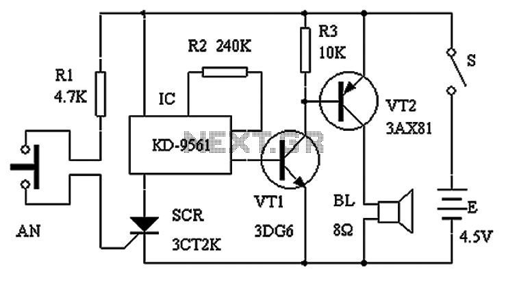
Normally closed contact burglar alarm circuit diagram
The circuit schematic presented in Figure 1 consists of an SCR, R1, and an AN SCR trigger switch circuit, along with an analog circuit composed of IC1, R2, VT1, VT2, and a BL siren. Typically, the circuit is designed to...
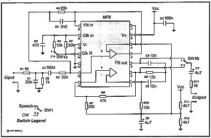
Speech Filter
A simple circuit that can switch between a sharp cutoff frequency above 2.5 kHz and a narrow bandpass filter around 800 Hz. In the low-pass (LP) state, it is suitable for speech applications as the filter section of a direct...
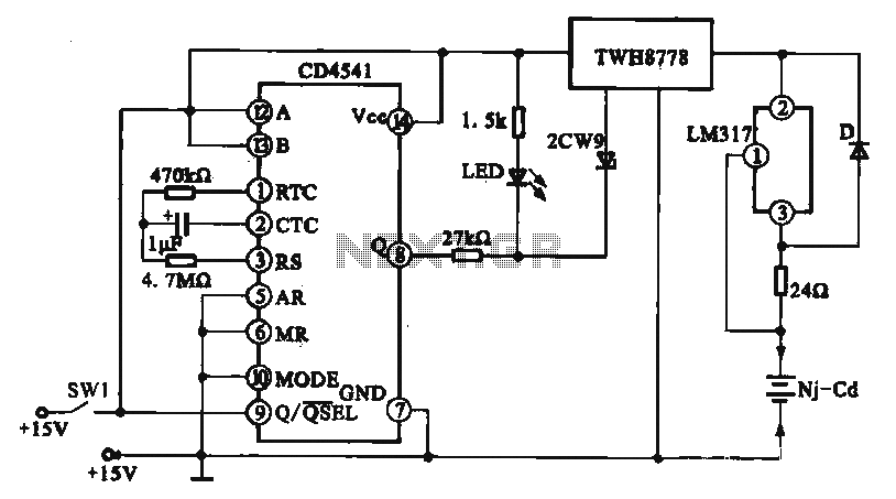
Constant current charging circuit long delay
A constant current charging circuit with a long delay is implemented using the CD4541, which constitutes a constant current charging circuit suitable for Ni-Cd batteries. Upon powering on, the CD4541 output at pin high activates the TWH8778 electronic switch, allowing...
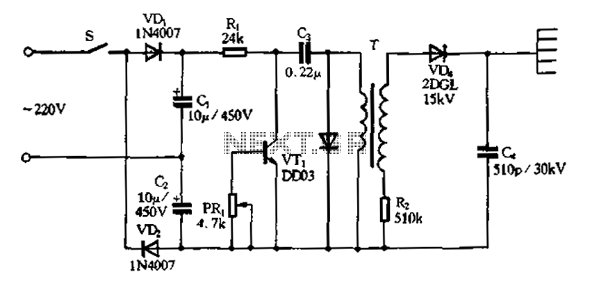
Doubling rectifier circuit in negative ion generator application circuit
Doubling rectifier circuit in a negative ion generator application circuit.
The doubling rectifier circuit is an essential component in negative ion generator applications, where it plays a crucial role in converting alternating current (AC) to direct current (DC) while also increasing...
Unusual Components and Applications
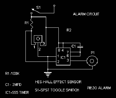
A common NPN transistor can be configured as a negistor by reversing its connections. The emitter connects to the power source via a resistor, while the collector connects to ground. In this configuration, the transistor demonstrates a phenomenon known as...
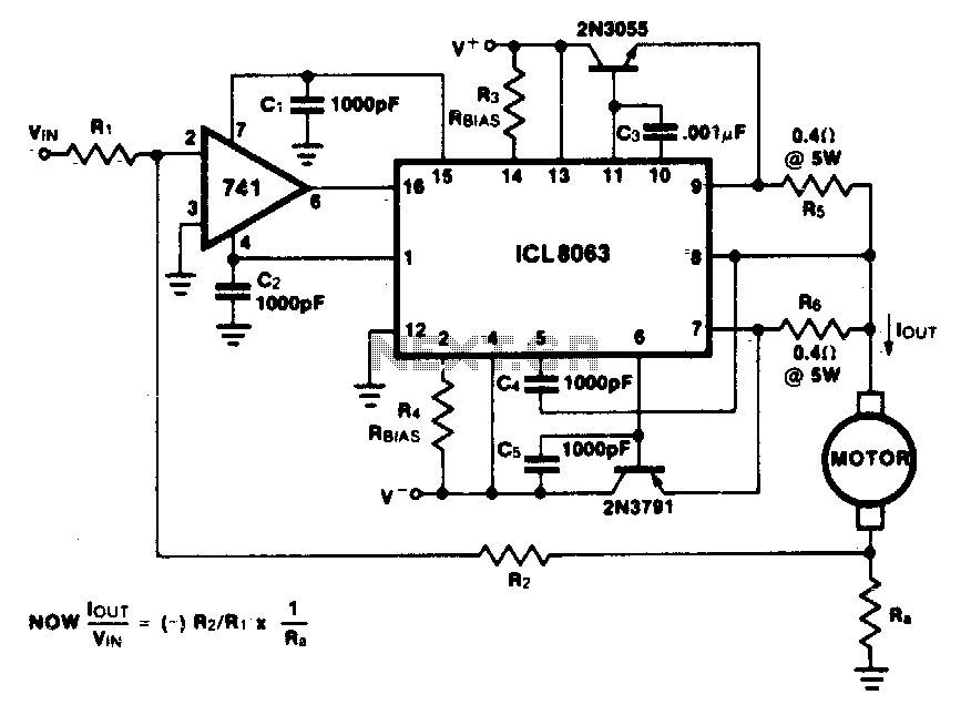
Constant current motor drive circuit
This minimum device circuit can be used to drive DC motors where there is some likelihood of stalling or lock-up. If the motor locks, the current drive remains constant, and the system does not destroy itself.
This circuit is designed to...
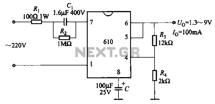
Adjustable output voltage power supply circuit MAX610
The output voltage can be calculated as follows: U = 1.3 (1 + R3 / R4) (V), where R3 and R4 are part of an adjustment potentiometer, allowing for a continuously adjustable output voltage.
The described circuit involves a voltage output...
Energy losses in modem
A toroidal transformer (2x12V 15VA) is utilized due to its significantly lower energy losses compared to an E-I core transformer, which was employed in the original mains adapter.
The toroidal transformer is a type of transformer that features a doughnut-shaped core...