


RC Charger
#RC charger
#charge current
#power dissipation
#voltage adjustment
#resistor
#battery
#13.8V
#R2
#R5
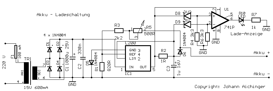
Description: Charge current: I=0.45V/R2 Power-dissipation by R2: (0.45 * 0.45 / R2) Please adjust 13.8V by R5 without connected battery. More: D1 - D4, D6: charge-current less than 1A: 1N4001 (up to 1N4007) charge-current up to 2A: 1N5401 D5: 1N4184, 1N4001. Transformer: 15 V max 2 A The L200 must be cooled.
The circuit described involves a battery charging system that utilizes a transformer, diodes, a variable resistor, and an L200 voltage regulator. The primary function of this circuit is to provide a regulated charging voltage to a battery while ensuring safe operating conditions for the components involved.
The charge current (I) is determined by the equation I = 0.45V/R2, where R2 is a resistor used to limit the current flowing into the battery. The power dissipation across R2 can be calculated using the formula (0.45 * 0.45) / R2, which indicates that the resistor must be rated to handle the calculated power without overheating.
To achieve the desired output voltage of 13.8V for charging, R5 is employed as an adjustable resistor. It is crucial to adjust R5 while the battery is not connected to prevent damage or incorrect charging conditions.
The diodes D1 through D4 and D6 are selected based on the charge current requirements. For charge currents less than 1A, diodes such as the 1N4001 through 1N4007 are suitable. For higher charge currents, specifically up to 2A, the 1N5401 diode is recommended. D5, which may be used for additional protection or regulation, can be either a 1N4184 or a 1N4001, depending on the specific circuit design and requirements.
The transformer is specified to provide a maximum output of 15V at 2A, which is adequate for the intended charging application. The transformer steps down the voltage from the mains supply to a suitable level for the charging circuit.
The L200 voltage regulator is a critical component in this design, providing a stable output voltage and current regulation. Adequate cooling for the L200 is necessary to ensure reliable operation and prevent thermal shutdown. This may involve using a heatsink or other cooling methods to maintain optimal operating temperatures.
Overall, this circuit design provides a robust solution for battery charging applications, with careful consideration given to component selection, current limiting, and thermal management.Charge current: I=0,45V/R2 Power-dissipation by R2: (0,45 * 0,45 / R2) ! Please adjust 13,8V by R5 without connected battery. D1 - D4, D6 : charge-current less than 1A: 1N4001 (up to 1N4007) charge-current up to 2A: 1N5401 D5: 1N4184 , 1N4001. Transformer: 15 V max 2 A The L200 must be cooled.
The circuit described involves a battery charging system that utilizes a transformer, diodes, a variable resistor, and an L200 voltage regulator. The primary function of this circuit is to provide a regulated charging voltage to a battery while ensuring safe operating conditions for the components involved.
The charge current (I) is determined by the equation I = 0.45V/R2, where R2 is a resistor used to limit the current flowing into the battery. The power dissipation across R2 can be calculated using the formula (0.45 * 0.45) / R2, which indicates that the resistor must be rated to handle the calculated power without overheating.
To achieve the desired output voltage of 13.8V for charging, R5 is employed as an adjustable resistor. It is crucial to adjust R5 while the battery is not connected to prevent damage or incorrect charging conditions.
The diodes D1 through D4 and D6 are selected based on the charge current requirements. For charge currents less than 1A, diodes such as the 1N4001 through 1N4007 are suitable. For higher charge currents, specifically up to 2A, the 1N5401 diode is recommended. D5, which may be used for additional protection or regulation, can be either a 1N4184 or a 1N4001, depending on the specific circuit design and requirements.
The transformer is specified to provide a maximum output of 15V at 2A, which is adequate for the intended charging application. The transformer steps down the voltage from the mains supply to a suitable level for the charging circuit.
The L200 voltage regulator is a critical component in this design, providing a stable output voltage and current regulation. Adequate cooling for the L200 is necessary to ensure reliable operation and prevent thermal shutdown. This may involve using a heatsink or other cooling methods to maintain optimal operating temperatures.
Overall, this circuit design provides a robust solution for battery charging applications, with careful consideration given to component selection, current limiting, and thermal management.Charge current: I=0,45V/R2 Power-dissipation by R2: (0,45 * 0,45 / R2) ! Please adjust 13,8V by R5 without connected battery. D1 - D4, D6 : charge-current less than 1A: 1N4001 (up to 1N4007) charge-current up to 2A: 1N5401 D5: 1N4184 , 1N4001. Transformer: 15 V max 2 A The L200 must be cooled.
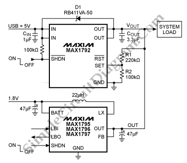
Automatic Switching for Battery USB Power Connection
This is a simple circuit for automatic switchover between battery and USB port. This circuit uses a more general step-up converter architecture.
The circuit designed for automatic switchover between a battery and a USB power source employs a step-up converter...
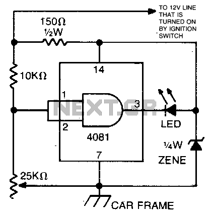
Car battery condition checker
This circuit utilizes an LED and a 4081 CMOS integrated circuit. A variable resistor is employed to adjust the voltage threshold at which the LED activates. The control should be set so that the LED illuminates when the voltage from...
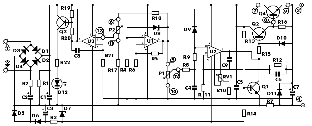
13.8V 20A power supply
The circuit safely delivers approximately 20 Amps at 13.8V. For lower current applications, a separate current limiting output capable of 15mA up to a total of 20A has been included. The power transformer should be able to supply at least...
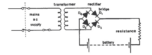
Battery Charging On Board Ship
Batteries serve as one of the energy sources available on vessels, utilized during blackouts and emergency situations aboard a ship. These batteries are employed for low-voltage DC systems, such as bridge navigational instruments, and must be kept charged to provide...
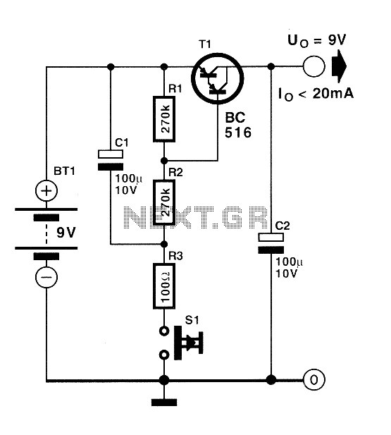
Automatic switch for batteries
Currently, batteries are becoming increasingly powerful, serving as the sole energy source for portable electronic devices. The rapid evolution of battery technology has prompted manufacturers of electronic equipment to strive for reduced power consumption in their products, enabling them to...
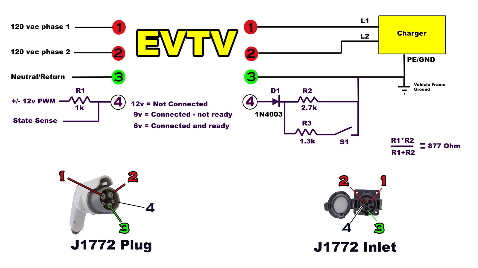
charging circuit
Building battery boxes for the Speedster. Although this topic may not seem thrilling, builders converting vehicles to electric drive often discover that the process of making a car run on battery power is relatively straightforward. However, about 50% of the...
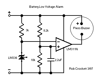
Precision Receiver Battery Low Voltage Alarms
Flying hand launch gliders necessitate the use of small-capacity receiver NiCad battery packs. While these lightweight packs are advantageous, they have the significant drawback of quickly depleting. Although careful timing of flights can be employed, it often results in either...
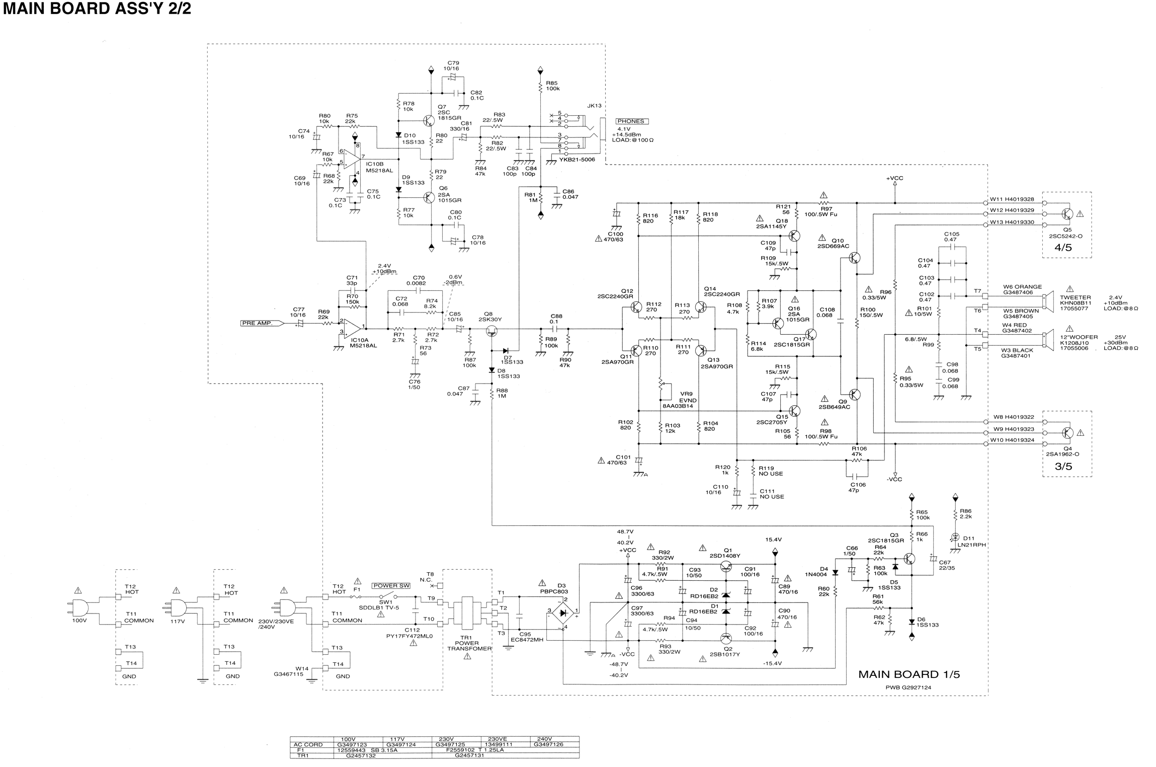
I burned out some resistors on the circuit board of my Roland
Some resistors on the circuit board of a Roland KC-300 amplifier have burned out and are so charred that their specifications cannot be determined. The resistors in question are R82, R83, R85, R92, and R93. Resistors R92 and R93 are...
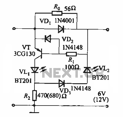
Battery state of charge indicator circuit
During the charging process, the green light-emitting diode (LED) VLi indicates that the battery is sufficiently charged, while the red light-emitting diode (LED) VLz illuminates when the battery is low.
The circuit involves two light-emitting diodes (LEDs) serving as indicators for...