


Simple Battery Charger With The Temperature Sensor
#LM350
#temperature sensor
#voltage regulator
#charging circuit
#battery management
#negative voltage
#IC
#power management
#thermal protection
#DIY electronics
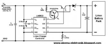
Description: The following circuit illustrates a simple battery charger equipped with a temperature sensor. This circuit is based on the LM350 integrated circuit. Features include negative...
The circuit utilizes the LM350 voltage regulator IC, which is known for its ability to provide adjustable output voltage and current regulation. The configuration includes a temperature sensor, which serves to monitor the battery temperature during the charging process. This is crucial for safety, as overheating can lead to battery damage or failure.
The primary components of the circuit include the LM350, resistors for setting the output voltage, capacitors for stability, and a temperature sensor such as the LM35, which outputs an analog voltage proportional to the temperature. The LM350 is connected in a typical linear voltage regulator configuration, where the input voltage is applied to the input pin, and the output voltage is taken from the output pin after passing through the resistive divider network.
The temperature sensor is connected to a microcontroller or comparator circuit, which can shut down the charging process if the battery temperature exceeds a predetermined threshold. This feature enhances the safety of the charging system by preventing thermal runaway conditions.
Additionally, the circuit may include LED indicators to show the charging status, as well as protection diodes to prevent reverse polarity connections. Proper heat sinking for the LM350 is also recommended, as the device may dissipate significant power depending on the input voltage and load current.
Overall, this simple battery charger circuit with a temperature sensor is an effective solution for safely charging batteries while monitoring their temperature to prevent damage.The following circuit shows about Simple Battery Charger With The Temperature Sensor. This circuit based on the LM350 IC. Features: negative ..
The circuit utilizes the LM350 voltage regulator IC, which is known for its ability to provide adjustable output voltage and current regulation. The configuration includes a temperature sensor, which serves to monitor the battery temperature during the charging process. This is crucial for safety, as overheating can lead to battery damage or failure.
The primary components of the circuit include the LM350, resistors for setting the output voltage, capacitors for stability, and a temperature sensor such as the LM35, which outputs an analog voltage proportional to the temperature. The LM350 is connected in a typical linear voltage regulator configuration, where the input voltage is applied to the input pin, and the output voltage is taken from the output pin after passing through the resistive divider network.
The temperature sensor is connected to a microcontroller or comparator circuit, which can shut down the charging process if the battery temperature exceeds a predetermined threshold. This feature enhances the safety of the charging system by preventing thermal runaway conditions.
Additionally, the circuit may include LED indicators to show the charging status, as well as protection diodes to prevent reverse polarity connections. Proper heat sinking for the LM350 is also recommended, as the device may dissipate significant power depending on the input voltage and load current.
Overall, this simple battery charger circuit with a temperature sensor is an effective solution for safely charging batteries while monitoring their temperature to prevent damage.The following circuit shows about Simple Battery Charger With The Temperature Sensor. This circuit based on the LM350 IC. Features: negative ..
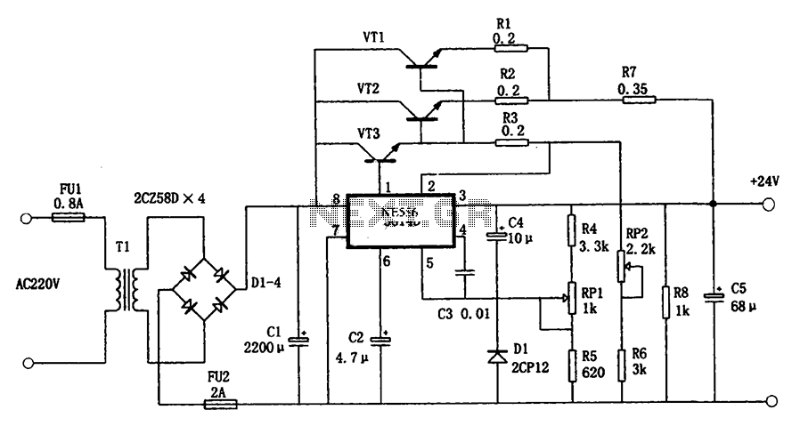
5G14D + 24V 1.9A power supply
The circuit illustrated in the figure is a +24V, 1.9A power supply design. It employs the 5G14D domestic integrated voltage regulator as the core component, supported by three external power transistors. While the 5G14D voltage regulator has a rated current...
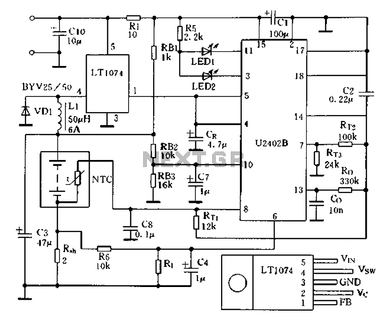
Charging circuit from the DC power supply switching power supply control
Charging circuit from the DC power supply switching power supply control
The charging circuit described is designed to operate with a DC power supply, utilizing a switching power supply control mechanism. This type of circuit is commonly employed in applications where...
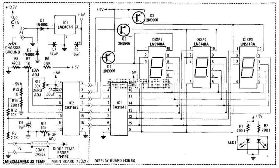
Digital Miscellaneous Temperature Gauge
A diode (IN4148) is utilized as a temperature sensor. IC2 is an A/D converter with BCD output. A reference voltage set by R7 is applied to the positive input of IC2. As the temperature rises, the voltage across the temperature...
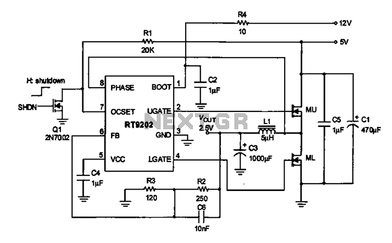
2.5V voltage regulator circuit
A 2.5V voltage regulator circuit is illustrated, which is part of a computer's motherboard. The circuit employs an oscillation circuit with the RT9202 control core chip, converting a 5V input supply into a regulated +2.5V output voltage, with the chip's...
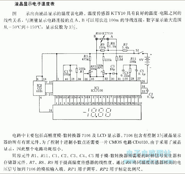
LCD electronic thermometer circuit
Related components PDF download: ICL7106CD4036. The LCD electronic thermometer circuit is illustrated. The temperature sensor KTY10 exhibits a strong linear relationship between temperature and resistance. Points A and B (Measurement display circuit) can be connected with a 100-meter wire. The...
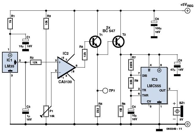
Detector circuit
This is an Overheat Detector Alarm Switch using the Temperature Sensor IC LM35. The core of this overheat detector (fire alarm) circuit is a precision integrated temperature sensor, the LM35 (IC1), which provides an accurately linear and directly proportional output...
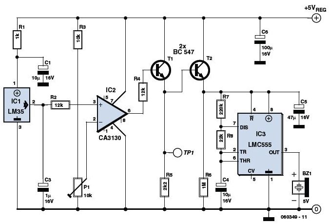
Overheat Detector Alarm Switch
The circuit utilizes a precision integrated temperature sensor, the LM35 (IC1), which provides a linear and directly proportional output in millivolts over a temperature range of 0 to +155 degrees Celsius. This sensor can be incorporated into fire smoke detectors,...
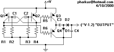
Negative Voltage Generator Schematic
Most operational amplifier circuits require a dual-polarity power supply - one having +V and -V. However, there are times when a DP supply simply isn't conveniently available. Single-polarity modifications to DP designs often achieve their effect by referencing the input...
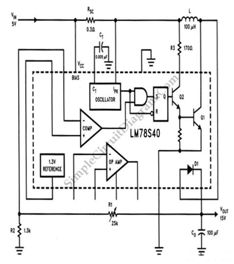
LM78S40 5V to 15V Step-up Voltage Regulator
A step-up conversion can be achieved without utilizing a transformer. This circuit is capable of converting a 5V DC source into 15V. It is important to note that there is no power gain.
The described circuit employs a DC-DC boost converter...