


simple lead acid battery charger circuit design
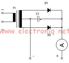
Description: This simple lead-acid battery charger requires a center-tapped transformer (12V 0V 12V) capable of delivering a current of 5 amperes, two diodes, and one capacitor. To charge the batteries, the positive and negative terminals from the charger must be connected to the corresponding terminals of the accumulator. When the batteries are depleted, the ammeter connected to the device will indicate a value between 1 and 3 amperes. Once the batteries are fully charged, the ammeter reading will approach zero, indicating that the charger can be disconnected from the accumulator.
The lead-acid battery charger circuit is designed to efficiently charge lead-acid batteries while ensuring safety and functionality. The center-tapped transformer provides the necessary voltage levels, producing a secondary output of 12V, 0V, and 12V, which allows for full-wave rectification. The two diodes are arranged in a bridge configuration to convert the alternating current (AC) from the transformer into direct current (DC), which is essential for charging the batteries.
The capacitor serves to smooth the output voltage, reducing ripple and providing a more stable charging voltage to the batteries. This is crucial for the longevity and health of lead-acid batteries, as excessive ripple can lead to gassing and damage to the battery cells.
The connection of the charger to the battery terminals must be made with care, ensuring that the positive terminal of the charger connects to the positive terminal of the battery and the negative terminal of the charger connects to the negative terminal of the battery. This correct polarity is vital to prevent damage to both the charger and the battery.
The ammeter is an important component of the circuit, providing real-time feedback on the charging process. When the batteries are in a discharged state, the ammeter will typically show a current draw between 1 and 3 amperes, indicating that the charger is actively supplying power to the batteries. As the batteries approach a fully charged state, the current will decrease, and the ammeter reading will approach zero, signaling that the charging process is complete. At this point, the charger can safely be disconnected from the accumulator, preventing overcharging and potential damage to the battery.
Overall, this simple lead-acid battery charger circuit effectively utilizes basic electronic components to provide a reliable charging solution for lead-acid batteries, ensuring proper operation and maintenance of the batteries throughout their lifecycle.For this simple lead acid battery charger we need a center tapped transformer (12V 0V 12V) which need to give a 5 amperes current, two diodes and one capacitor. To charge the batteries we need to connect the terminal + and - from the charger to the same terminals form accumulator.
When the batteries is empty the ampere-meter connected to the devic e will indicate a value between 1 and 3 amperes, if the batteries are charged the value which is indicated on ampere-meter is almost zero and the charger can be unplugged form accumulator.
The lead-acid battery charger circuit is designed to efficiently charge lead-acid batteries while ensuring safety and functionality. The center-tapped transformer provides the necessary voltage levels, producing a secondary output of 12V, 0V, and 12V, which allows for full-wave rectification. The two diodes are arranged in a bridge configuration to convert the alternating current (AC) from the transformer into direct current (DC), which is essential for charging the batteries.
The capacitor serves to smooth the output voltage, reducing ripple and providing a more stable charging voltage to the batteries. This is crucial for the longevity and health of lead-acid batteries, as excessive ripple can lead to gassing and damage to the battery cells.
The connection of the charger to the battery terminals must be made with care, ensuring that the positive terminal of the charger connects to the positive terminal of the battery and the negative terminal of the charger connects to the negative terminal of the battery. This correct polarity is vital to prevent damage to both the charger and the battery.
The ammeter is an important component of the circuit, providing real-time feedback on the charging process. When the batteries are in a discharged state, the ammeter will typically show a current draw between 1 and 3 amperes, indicating that the charger is actively supplying power to the batteries. As the batteries approach a fully charged state, the current will decrease, and the ammeter reading will approach zero, signaling that the charging process is complete. At this point, the charger can safely be disconnected from the accumulator, preventing overcharging and potential damage to the battery.
Overall, this simple lead-acid battery charger circuit effectively utilizes basic electronic components to provide a reliable charging solution for lead-acid batteries, ensuring proper operation and maintenance of the batteries throughout their lifecycle.For this simple lead acid battery charger we need a center tapped transformer (12V 0V 12V) which need to give a 5 amperes current, two diodes and one capacitor. To charge the batteries we need to connect the terminal + and - from the charger to the same terminals form accumulator.
When the batteries is empty the ampere-meter connected to the devic e will indicate a value between 1 and 3 amperes, if the batteries are charged the value which is indicated on ampere-meter is almost zero and the charger can be unplugged form accumulator.

OverUnity Lead Acid Battery Switching Self Battery Charging
The only way to determine how quickly a specific battery can recharge is to place it under load, adjust the switching frequencies, and vary the on/off times, then plot the results. A circuit drawing 0.5 Amps at 12 Volts will...
Capacitor Charger Lead Acid Battery
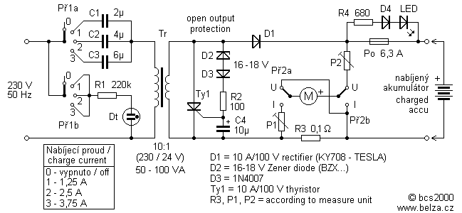
Leaving aside the complex chargers, "stuffed" electronics capacitor charger is one of the best connections. Charging current is limited by the resistor (or other element of the changing excess energy into heat), but the reactance of the capacitor to the...
Very Simple Lead Acid Battery Charger with PB137 Regulator
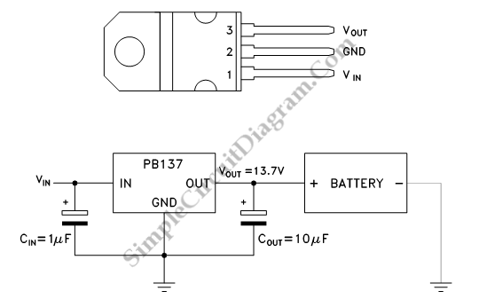
This is a straightforward circuit designed for charging lead-acid batteries using the PB137 regulator. The PB137 is utilized in the lead-acid battery charger circuit due to its ability to provide...
The PB137 voltage regulator is a linear regulator specifically suited for...
Open and Short Circuit Test on Transformer
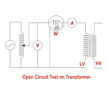
Open and short circuit tests on a transformer are conducted to determine the equivalent circuit of the transformer, assess its voltage regulation, and evaluate its efficiency.
The open circuit test is performed by applying the rated voltage to the primary winding...
ELF MONITOR
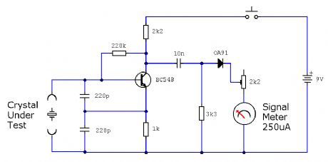
The capacitor instrument is not intended for measuring the capacitance of capacitors; rather, it is designed to identify whether a capacitor is functional or defective, as well as to detect short circuits or open circuits. This functionality provides reliable quality...
Control cables plus anti-interference capacitors
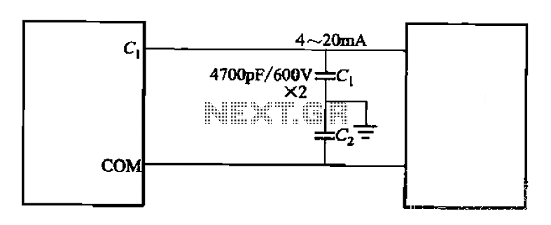
A capacitor filter is utilized in frequency control circuits and is a common method for implementing anti-jamming measures. It addresses frequency interference noise within the wiring of the 4-20mA control loop. The anti-interference is achieved through bypass capacitors C1 and...
Multi-output power supply circuit
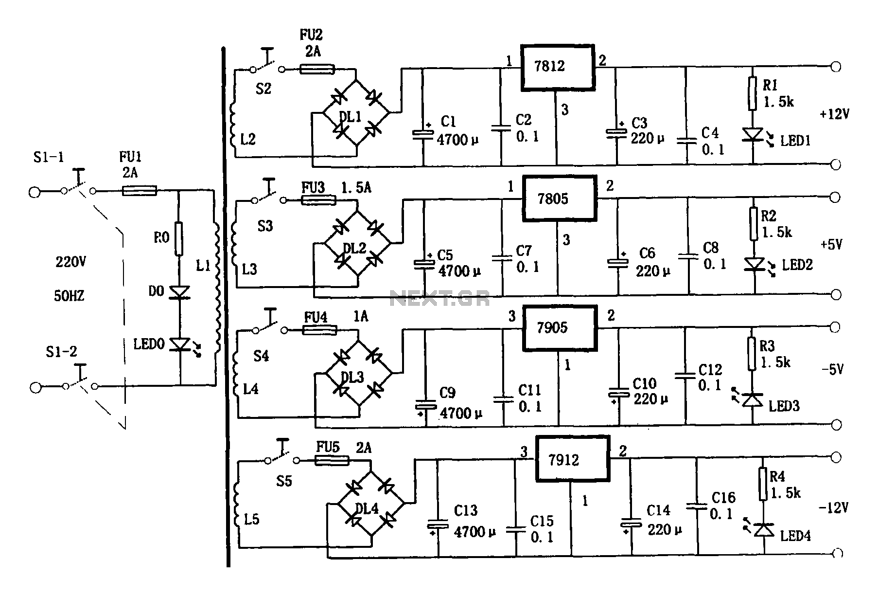
This document presents a multi-output power supply circuit. The circuit utilizes the secondary winding of a transformer and incorporates four voltage regulators: 7812, 7805, 7905, and 7912, providing independent output voltages of +12V, +5V, -5V, and -12V, respectively. Each output...
Automatic lighting control telephone signals
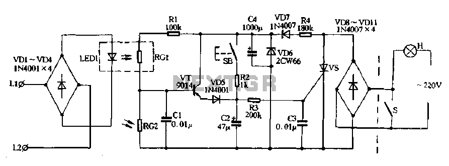
Diodes VD8 to VDI1 function as part of the main circuit isolation, with SCR serving as a composition control switch. The buck regulator circuit is composed of a stable orbital tube VD6 and a simple resistor-capacitor combination (C4). The circuit...
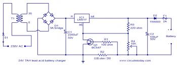
24v lead acid battery charger diagram
To set up the charging voltage, power on the charger and connect a voltmeter across the output terminals. Adjust R4 until the voltmeter reads 28V. The charger is now ready for battery connection.
The charging circuit described involves a voltage regulation...